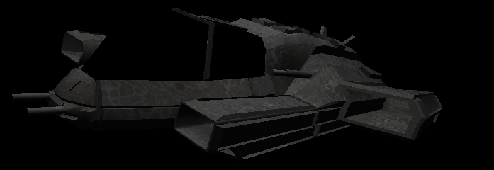
Author Topic: A complete FS ship tutorial -- EXTREMELY IMAGE HEAVY  (Read 31640 times)

0 Members and 1 Guest are viewing this topic.

Offline ShadowWolf_IH

  • A Real POF Guy
  • 211
    • CoW
A complete FS ship tutorial -- EXTREMELY IMAGE HEAVY
This tutorial should get you started on building ships and getting them into FreeSpace. It will cover the whole process, from starting to model in Blender all the way to converting and testing.   This tutorial doesn’t rely on the one created by FreeSpaceFreak, it is his tutorial with additions and upgrades for a newer blender version.  Further additions include texturing as taught by mjnmixael, and PCS2.  The final addition will be me turning this entire escapade into a walkthrough of modelling a ship, UVing it, texturing it, creating the pof for it, and tabling it.  Basically we are going to go from opening blender, to opening Freespace.

We will model, UV map, texture, convert, table and test a light bomber.  Normally you will work in greater detail than this (which is admittedly ugly), but this isn‘t for releasing, it is for you to learn on, and to encompass what people taught me outside of the original tutorial:


  For this tutorial you will need the following:

Blender (latest version).
Gimp (latest version)
PCS2 (latest version)
pilot model
FreeSpace 2 (you’d better have this)

Table of Contents (links)

To use this Table of Contents, know the following.  Chapter Headings in Green are links to the respective posts, while sub headings in Yellow are specific items found in each chapter.  Red means it hasn't been done yet.

Chapter 1 (This Post)
Welcome
What you will need
1.  Modelling
1.1 Blender Interface
1.2 Modelling Basics
1.3a  Build a ship then add a pilot model


Chapter 2
1.3b Grow your ship around the pilot  (Walkthrough)

Chapter 3
1.4 Mesh Problems
1.5 Greebling


Chapter 4
1.6 UV
1.6a UV: A word of explanation
1.6b UV Walkthrough
1.7 AO Bake
1.7a AO Bake how to
1.7b AO Bake Walkthrough


Chapter 5
1.8 LOD, Debris, Shield
1.8a LOD, Debris, Shield How to
1.8b LOD, Debris, Shield Walkthrough
2.0 Conversion
2.1a Hierarchy
2.1b Hierarchy Walkthrough
2.2 Texture precautions and convert


Chapter 6
3.0 Texture
3.1 Base texture (Diffuse) Walkthrough
3.2 Glow Map Walkthrough


Chapter 7
3.3 Shine Map Walkthrough
3.4 Normal Map Walkthrough
3.5 -trans map Walkthrough


Chapter 8
4.0 PCS2
4.1a PCS2 How to
4.1b PCS2 Walkthrough
5.0 Tabling


Chapter 9
6.0 Advanced
6.1 Turrets

6.2 Animated modelling
6.3 Visible missiles
6.4 Animated Textures


Chapter 10
Credits


1. Modelling

For the modelling, we'll be using Blender, because it's arguably the best free modelling program out there. Yes, the interface may take a while to get used to, but you'll eventually grow to love it. The hands-on-mouse-and-keyboard controls make for a really fluid workflow.
We'll be doing this in Blender 2.66.


1.1 The Blender interface

So, install the latest version of Blender (http://www.blender.org/) and start it up. You should be seeing something like this.


Looks scary? It's not as complicated as it seems. The interface consists of different windows, each with their own use. What you see here is the default layout; you can change a window type by clicking on the window type buttons, marked by the arrows in the following figure. You can also change the window sizes by simply dragging the boundaries.
In case you press a wrong button, and things are suddenly all screwed up, simply press Ctrl-N to reset everything, confirm with Enter (or LMB, left mouse button).


Windows become active when you hover over them; the header of the active window will brighten a little. This is important, because the same keyboard shortcut can have different functions in different windows. So if you press a shortcut, always make sure your mouse is inside the right window.

  • 3D View window: This is the window you'll be working in most. The large window shows what you're building: the cube in the centre is the default object, the black-wire thing on the left is the camera and the round thingy on the right is a lamp. The camera and the lamp are only used for rendering, we won't need it for making a ship.
    Everything in Blender has x,y,z coordinates, according to the x,y,z axes in the bottom left. The grid lies at z = 0; the red and green gridlines correspond to the X and Y axes, respectively. So yes, the cube's centre (the orange dot) lies at coordinates 0,0,0.
    You manoeuver around your scene by MMB (middle mouse button) dragging, shift-MMB-dragging and Ctrl-MMB-dragging (or scrolling). Try it.

    The "Object tools" panel on the left of the 3D window has a few of the commonly used controls. To try them out, make sure you still have the cube selected, you can tell by the orange outline. Else, right-click it to select it again.
    • Translate, Rotate and Scale do exactly what you think they do, try them out. Their shortcuts are G (for "Grab"), R and S respectively.
    • "Origin" will shift the cube's origin, we'll get to that later.
    • Duplicate (Shift-D) and Delete (X or Delete keys) will do exactly what you think they do.
    • Join (Ctrl-J) will merge two objects (select multiple objects with Shift-RMB (right mouse button)).
    • Shading (Smooth/Flat) will change the smoothing of your model, we'll get to that later.
    • Keyframes you only need if you're making an animation, leave them alone for now.
    • Repeat Last will do again what you last did - useful for placing a row of turrets, for instance. With History you can choose which action to repeat.
    • Grease Pencil... I dunno what that's useful for. We won't be using it.

    At the bottom of the 3D window, you can see the header - it contains more controls and submenus. I won't cover all of them here, I'll point out the ones you need later.
  • Info window: kind of like the menu in Blender. It contains modes, controls, options etcetera. File is the most important menu, it contains Save, Open, Close, Import and Export, etcetera.
  • Outliner window: This shows the hierarchy of your ship. For turrets, subobjects etcetera, you'll need to set it up right. But of course, you need a model first, so we'll get to this later.
  • Properties window: Shows properties of your model. The different tabs contain different property sets; hover over the buttons to see the different ones. The one that we'll be using most for shipbuilding is Modifiers.
  • Timeline window: This is used for making animations, we don't need it for shipbuilding.If you want it out of the way, click the corner thingo at the top-left, drag it over the 3D window, then back over the timeline window and release.

This is about everything you need to know about the interface; we'll now proceed to the actual modelling.

1.2 Modelling basics

There are two distinct ways of viewing a 3D environment; isometric or perspective. Here's an image showing the difference. Isometric is the most convenient for modelling, since there is no distortion; however, perspective is how stuff looks in real life. You can switch between the two modes by pressing Numpad 5; observe the change in how the grid looks. For now, we'll use isometric mode.

Blender can visualize your model in different ways; the two we'll be using most are solid (which you're in now) and wireframe. Switch between them with the Z key, or the menu marked "display mode selector" in the second figure.

Now, axes are important for shipbuilding. For proper conversion, your ship will be pointing along the Y axis, with the top pointing to the Z axis - remember that you can see the axes in the bottom-left of the 3D window. There's a few controls that will make you look directly at one side of the model; numpad 3 should show you the side , num 7 the top and num 1 the back, as shown in the pictures below. Ctrl-numpad 1,3 or 7 will show you the opposite side. Note how the axes in the bottom left are different for each view.


Blender has different modes; in each mode, you can do different things to your model. The two main modes are Object mode and Edit mode; you can quick-switch between them with the Tab key. The current mode is shown in the mode selector, in the header of the 3D window. Object mode lets you play with objects; move, rotate and scale them duplicate and join them, etcetera, like you've already done. Editmode lets you actually change the mesh of the objects (the mesh is the arrangement of vertices (points), edges (lines) and faces (planes) that together make the whole shape of the object.

So, let's try editing the cube. Select it, and press tab to go to Edit mode. Your 3D window should now look similar to the following figure; note that by default, you have the whole mesh selected.


Press A to deselect everything, then right-click one of the corner points to select it. You may have some problems selecting the point you want; this is one of the few things that don't work quite right in Blender. Switch to wireframe mode (Z key) to circumvent the issue.

With a vertex selected, you can now alter the physical shape of the cube. Press G and move the vertex around to position it somewhere else. Select multiple vertices (Shift-RMB) and you can scale (S) or rotate (R) them. If you want to perform an action along a predefined axis (say, moving along the X axis), press the axis key (X, Y or Z) while moving stuff about. If, on the contrary, you want stuff to not move along a certain axis, press Shift-<axis key>. You can use the three buttons marked "Selection modes" (or Ctrl-Tab) to select and transform different kinds of elements. Play around with this a little to get a feel for it.

Now, of course, you're not gonna be able to make a ship with just six vertices; you'll need some more freedom. Select an edge and press W -> Subdivide. Lo and behold - you now have more possibilities to play around with! But it's still kind of limited. This is where extrusion comes in. Select a face and press E; you can now move the face along its normal, making new faces along the bounds. And you can do this again and again and again. Believe it or not; this is how we make ships for FS.

Of course, there are a couple more useful tools, each with their own shortcut:
  • F: Make a face between the selected vertices or edges.
  • Alt-M: Merge selected vertices together.
  • Ctrl-T: Triangulate a quadrangular face.
  • Alt-J: Merge two adjacent triangles into a quad.
  • Ctrl-E -> Edge loop/ring select: selects edge loops or rings based selected edges.
  • O: Proportional editing, useful for smooth-looking (e.g. Vasudan) ships. See here for getting started with it.
  • And many more; you'll find out about them as you grow more experienced.

There's one more feature we'll be using a lot: Modifiers. They are a way of altering your model, without actually changing the mesh itself. The changes only become final when you apply the modifier. The Mirror modifier is one of the most useful ones. If you want to make a symmetric model (most FS ships are, so chances are your design is symmetric as well), you only need to make half the model; the Mirror modifier will do the other half of the work.

So how does it work? Let's first clean up a little: go back to Object mode (Tab key) and press Ctrl-N. This will get rid of everything you've done, and you can start again with a clean sheet. Select the cube again, go to editmode. Select the four edges that cross the Y-axis (the green line), parallel to the X-axis (the red line), like in the figure below. Press W -> Subdivide; the four edges are now neatly cut along the YZ-plane, which will also the symmetry plane of your ship.


Select the four vertices on one half and delete them. You'll have half of a hollow cube left.


Now in the Properties window, click the tab with the wrench on it; this is the Modifiers tab. It's currently empty, because there are no modifiers associated with the half-cube. So click Add Modifier, and (under Generate) click Mirror. (Yes, there's all kinds of fun modifiers in there, but we'll only be using two for shipbuilding.) Now, the other half of the cube will magically reappear, but you can't select it. Why not? Because it is simply the mirrored version of the half that you can edit. So, grab a vertex and move it around - the mirrored half will remain symmetric at all times. Neat, huh? This reduces the workload of making a ship by half - if it's a symmetric ship, of course.

We shall now proceed to actually modelling a ship. In case you still feel a bit uncomfortable with modelling, or haven't gotten the hang of it yet, take a look here for a more exhaustive walkthrough; come back here when you feel ready to start working on your first ship.

1.3 Your first ship

We'll start off with something relatively simple, a bomber. Capships require a different (and more complicated setup), I strongly suggest that you start off simple with a bomber. Don't be overambitious, it'll kill your motivation - trust me, I know.

There are two different ways to start.  You can build your ship and then add a pilot, or you can start with the pilot and grown your ship around it.  I am including the first way,  1.3a, in order to show you how, but we will be using the second way, 1.3b, or growing the ship around the pilot model.  Even though we will be going through 1.3b, please perform the exercises in 1.3a, as they lay a solid foundation.  It won’t take but a few minutes, and will stop countless hours of frustration. 

If you choose to go the way of 1.3a, when you are finished, you can skip 1.3b, 1.4, and 1.5 and go directly to 1.6.

In Object mode, press Ctrl-N to clean up (you don't need to do this if you just started Blender). Select the cube and go to editmode; select all vertices and delete them, so you have an empty mesh. Press Num 5 for orthogonal view, then Num 3 to look at the side of what will become your ship. Add a Mirror modifier.

Now, make sure that you're in Vertex select mode, then Ctrl-click to make vertices appear on the working plane. Each successive vertex will be connected to the currently selected one, so just placing a row of Ctrl-clicks will give you something like this:


This will be the start of the cockpit glass. Go to top view (Num 7), select all vertices and start extruding, dragging, rotating them. Like this.


Now, if you go back to shaded view (press Z, remember?) and take a look at what you have so far, it probably looks faceted. Not smooth, like a cockpit should look. So let's take care of that, or it will look the same way in-game. Go back to objectmode and, in the "Object tools" panel on the left of the 3D window, press the "Smooth" button. Hum... chances are it still looks weird. At least this one does. So go back to editmode, select all and press Ctrl-N. This will make sure that all faces are facing the same way. Now it should look okay; still a bit odd, but better nonetheless. It'll look better in-game.


Before I forget it: don't forget to SAVE YOUR WORK OFTEN, with Ctrl-S. Blender hardly does autosaves, and it doesn't ask you if you want to save your changes before closing. It assumes you're competent enough to do that yourself if you want to. There is a File -> Recover last session, but don't count on it too much. Save often.

Now, the cockpit has to end somewhere, with a crisp edge. How are we gonna do that? With another modifier. Extract your cockpit glass to form the edge, set everything smooth again and add an Edge Split modifier. This will automagically "break up" your mesh when it makes an angle sharper than x degrees; you can set the split angle in the modifier panel. For old-school, blocky Terran ships, the default 30 degrees usually works well. Since I'm modelling an Ancient ship for this tutorial, with a lot of smooth lines, I'll be using 50 degrees here.


And well, there you go. From here on, you just extrude, grab, rotate, merge, etc. etc. etc. until you have the design you had in mind. I can't help you with that, it's all yours. I can only give you a few general guidelines on this:
  • It's a game, everything needs to be rendered at a high pace. Don't overdo it with polycount. It may be cool to spend hundreds of polies to make something look perfectly flush, but people will only notice the difference by their FPS counter. Take this sphere, for instance; the difference is nearly a factor 10 in polycount, while it won't be noticeable in-game. For capships, which move very slowly and can thus be admired in detail, you could get away with the left one, but don't overdo it on a fighter.


  • Try to work with quadrangles and good topology. It will help a lot with the modelling itself, with possible lighting issues and with LODing, which we'll be doing later. For a more complete explanation, see here (thanks to Thaeris for writing it all down), but the image below should give you an idea: the left mesh has good topology - see how all the quads are neatly aligned, like a grid - while the right mesh has a messy topology, with lots of triangles and highly distorted quads.
    However, do keep in mind that you're modelling for a game - trade off polycount versus topology. The thingo on the left would be a serious performance hitter if it were ported into FS.


  • Your model should preferably consist of a single, connected mesh - what we call a manifold. BUT, you should only do this in as much as this doesn't jeopardize the previous points. You'll need a bit of good judgement on this; don't worry, as you grow more experienced, you'll get a feel for it. I hope the picture below explains it well enough.


  • Don't model your entire ship in one go. It's good to take a break every once in a while; you'll then come back to the model with a fresh mind and good ideas.

  • Ask for external feedback: show people your WIPs and ask them for their opinions. They might see things that you hadn't even thought of.

Come back here when your mesh is done, and we'll talk about unwrapping. Here's a quick overview of how this mesh evolved from the simple row of vertices above to a full-on fighter/bomber:


« Last Edit: June 15, 2013, 07:25:29 pm by ShadowWolf_IH »
You can't take the sky from me.  Can't take that from me.

Casualties of War


Offline ShadowWolf_IH

  • A Real POF Guy
  • 211
    • CoW
Re: A complete FS ship tutorial -- EXTREMELY IMAGE HEAVY
1.3b  Growing your ship around the pilot

Ok the first thing we will need to do is open blender.

If you have been screwing around and such, please close blender and reopen it.  Get rid of the splash screen by clicking somewhere other than the splash screen.  You should see the box highlighted orange.


Currently you are in object mode, switch to edit mode and  hit “delete“, then “vertices“.  The box should now be gone.

If you haven’t already done so, download  “Pilot” model from http://casofwar.hard-light.net/images/Pilot.rar.

Open Pilot.blend and you will see an untextured version of the Pilot model.


Before we go any further let’s make sure we are truly seeing the same thing.  I prefer to work in Isometric (ortho) view, so hit numpad 5 and look at the top left of your work window, it will tell you which view you are in, just keep hitting it until it says (view direction) ortho, where view direction may be right, top, front, etc.

We need to go into Edit mode to select some of the vertices.  When you change from Object to Edit, all of the vertices may be selected, if this is the case hit “A”.  Then none will be selected.  “A” is pretty handy no matter what mode you are in.  If you are in Object mode it will select everything in the layer, if in edit mode it will select all vertices, if in UV mode....well you get the picture.  If nothing is selected, hitting “A” will select everything, conversely, if there is anything (or everything) selected, hitting “A” will deselect it.

So lets go ahead and start selecting vertices.  Hit numpad 7 to go to topview, and then use the scroll on your mouse to zoom in a bit.  I generally don’t zoom in this much, but I wanted you to clearly see the vertice that I have selected, select it now by right clicking on it.


We are going to select other vertices as well as this one.  Hold down the shift key while selecting the vertices, and it allows you to select more than one.  Select all of the vertices which go from the middle to the right, and down the right side.  See the following image.


Hit numpad 1 to bring up the rear view, and you should see orange lines heading toward the vertice you want, those lines come from vertices already selected.  The thing you need to remember here, is to hit shift before you right click that vertice.  Do it now, and you should see the following.


Now I am going to show you what would have happened if you had selected that vertice without holding the shift key.  Select that vertice by right clicking. Notice how that vertice is now the only one selected?  That’s not what we want, so simply hit CTRL Z to undo.  You now have all of the vertices selected again.  Trust me, you will become quite well aquainted with CTRL Z.

Moving on...

What we are wanting to achieve is simple.  We need our model to encompass the pilot submodel (it will be a submodel), but not be “attached” to it.  Why, because it already has a UV map and texture. 

So how do we do that?  It is very simple,  SHIFT D.  Hit SHIFT D and then move your mouse, but do not click anywhere.  Notice how our duplicate moves with the mouse, we don’t want that.  Right click.  If you accidentally move something somewhere, you can simply right click and it goes back to where it was.  The best thing to do when you don’t want to move your duplicate is to hit SHIFT D, and then don’t touch the mouse, hit ESC.  Then it won’t move.

Anyway, we now need to separate our duplicate from the pilot, so next to your mode button (currently says edit mode), you will see a menu called “mesh”.  Hit it, and then select vertices, separate, and finally,  selection. 

Mesh>Vertices>Separate>Selection.

Our duplicate is no longer attached to pilot, unfortunately, we can’t do anything with it.  We have to select it.  So change from Edit mode to Object mode.  Notice that orange line completely surrounding the pilot model, that means that currently, it is the object selected.

Right click on the right half of the model, and notice how the highlighting (orange outline) changes.  This is because we now have our duplicate selected.  Go back into Edit mode, this is where the fun really starts.

Select the last vertice that you selected before separating things(the vertice is selected in the image below), and delete it. The only reason that we selected it at all was to make things easier when we selected our separated object.


With that vertice deleted, select the vertices that I have selected in the following image.


We want to build a small buffer zone where the ship and the pilot model come together.  To do this, you are going to hit E (extrude).  Then hit ESC.  Because our edges would want to extrude in different directions, things would look funky if we extrude them in the normal manner.  So we extruded, and now have created faces with no area.  So let’s scale it up.hit S, and give it a little height. Use your mouse to adjust the scaling, when finished, left click to lock it. See below.


We have a problem with a specific vertice.  It needs to be on the centerline, and it isn’t.  You’ll run into this a lot.  The vertice is selected in the image below.


So press N to bring up properties, and notice at the top of the new window it says “Transform”, and beneath it is “Vertex” and three coordinate windows.  Change the coordinate for “X” to zero (0) and hit enter.  See below.


The thing about this that you need to remember, is that if you select mroe than one vertice, you are chanigng the median coordinate, which moves each coordinate an amount based on the median of them both, you are not setting both coordinates to zero (0).

Notice that the vertice is now lined back up on our centerline.

Moving on.  Let’s start modelling the body shall we?    90% of what we do will be extruding. The nice thing is, you can extrude to where you want, where the computer wants, or along a specific axis. 

Go ahead and hit N again to close the properties window.  Now we need to add some modifiers.  Let’s go back to Object mode for a moment, all the way to the right is the properties window.  Notice how I have the wrench highlighted?  Click it, then click ADD MODIFER, and select MIRROR.  This creates a mirror image of what we model, which cuts our workload in half.  Nice.  With that done, click ADD MODIFIER again, and this time select EDGE SPLIT.  Then go back to Edit mode.  See below.


ok, let’s go ahead and start extruding our model.  Select the vertices that I have selected below.


Numpad 7 to bring up the top view.  When we extrude this time we want to hit E for extrude, then Y, so that we extrude on the Y axis. See the following image.


Select the three vertices in the front by Right clicking one of them, and then Shift Right clicking  the other two, now those three are selected and the ones in the back are not.  Numpad 3 to bring up the side view, and then extrude on the Z axis by hitting E, then Z.  Then grab the new vertices by hitting G and drag them forward on the Y axis by hitting Y and moving the mouse.  Should look like the image below when done.


Rotate your model slightly, by holding your Middle mouse button (or scroll wheel), and simply moving the mouse until you can see the four vertices running down the side, then select them. See below.


Bring up the top view.  We are going to extrude the selection along the x axis.  Hit E for extrude, and X to make it axis particular.  See below for my extrusion.


Hit numpad1 (even though the view says front, I think of it as rear, because it is what I am seeing), and we are going to drag the selection down by hitting G to grab the selection, and Z to lock in the axis,  See below.


Swing the model around again to what I call the ¾ view, and select the vertices that I have selected, notice in the image below that I have a face there and you don’t.  Create one by hitting F.


Select the vertices that I have selected below.


Bring up the side view and the we will extrude down and drag forward.  So extrude along Z, then grab and hit Y to drag them forward.  See below.


Ok this is important, select the vertices that you see below, and make a face out of them by hitting F. 


When you created your face did you notice how it is twisting?  We are asking that face to do too many things all at once.  It will stretch the texture and look horrid.  So how do we defeat this?  Open the Mesh Menu, then Faces, then Triangulate Faces.  For the most part you want to stick with quadrangles instead of triangles, but every once in a while, it’s ok.
See below.


Before we go any further, let’s smooth things out a bit.  Go back into Object mode and see the image below for where to look  (look to the left).  You will see a subsection called “Shading” with two options, “Smooth”, and “Flat”.  Choose smooth, then go back into edit mode.  You won’t see much of a difference in the half that we work on, but rotate the model around to look at the other side, it should look much smoother now.


ok back to 3/4 view.  While you were rotating the model around did you notice how the edge in the front was very hard?  I don’t like it so we are going to fix that.  Select the vertices that I have selected below.


On the left side menu, as you scroll through, up above where you found the subsection called “Shading”, you will find a subsection called “Add.”  Under that heading you will find an option called “Subdivide.”  Once you hit it you’ll see what it does, it is self explanatory.  It is also useful for dividing a single edge into two equal parts.  Anyway, once you have subdivided, start manipulating your vertices by grabbing them and moving them along the x axis and/or the y axis until you get something like what you see below.  It will be sort of domed sort of not, you’ll get the feel.  It will take a bunch of ratoting of the model to see the views you want, as well as hitting numpad7 and numpad3.  NOTE:  DO NOT TOUCH THE VERTICES THAT ARE HIGHLIGHTED BELOW.  IF YOU DO YOU RUIN THE JOINT WHERE THE PILOT MODEL MEETS THE SUBMODEL THAT WE ARE CURRENTLY WORKING IN.


Before we go any further, I am not sure how others check to see if their normals are right, but the way I do it is to go into Texture mode.  Think of normals as “the direction each face is facing.”  We need to make sure that they are all facing outward, otherwise when we go into PCS2, they will be invisible.  So....go into Texture mode, and you will see that we have some faces “missing” which means that some normals are reversed.  See below.


Once again we go into Edit mode and highlight those faces.  Look to the left, and while scrolling you will find a subsection called “Normals” that has two options: “Recalculate” and “Flip Normals”.  Select “Recalculate”, and then go back into Texture mode and take a look.  They should be cleared up.  Sometimes Recalculate doesn’t handle it, so we then need to flip the normals, but I will show you an example of that later.  Before continuing on, rotate your model around while in Texture mode and take care of any normals that need help. You may want to switch into “Face select”.  You basically have 3 options, Vertice, Edge or Face.  You can switch between them by going to the section shown below.


Now we can continue with the model itself.  Go back to Vertice Select, and select all of the vertices shown below.


Extrude them along the Z axis, and then select the vertices shown below so that we can take care of that hard edge.


Drag them outward along the X axis until the harsh horizontal line is smooth.With that done, we will work with the two vertices shown below.  Grab the top most one and drag it along the X axis toward the center of the model until the harsh verticle line is smooth, then Grab the bottom vertice and drag it over as well, if you pay attention to the face that these vertices attach to, the one that runs down the side, you will see it slightly discolor as you move the top vertice in.  Near as I can figure, that discoloration means that you are twisting the face, so by bringing the lower vertice inward as well, you will see that discoloration go away, at that point you have gone far enough.


Grab the vertices shown below, and go to your side view, Extrude them on the Z axis about the same distance as the section above them, then rotate the model until you are looking pretty much at the front.  With this done I want you to Grab them and drag inwards along the X axis.


I wanted that angle to be harsh for the shape of our nose, so now it is.  Select the three vertices that you see below and create a face out of them by hitting F.  Then select the very bottom vertice of the new face.  See below.


Remember when we we used a coordinate to move that one vertice?  We are going to perform a similar operation in a few moments.  Select the vertice that I have selected below.  Hit N to bring up properties, and highlight the Z coordinate.


CTRL C to copy that coordinate, and then select the three vertices highlighted below.


Extrude these vertices along the Z axis, to about the same hieght as the one whose Z coordinate you copied.   Then select any of the three vertices and use CTRL V to paste the coordinate that you copied into that Vertice’s Z coordinate.  Then do the same thing for each of the other two vertices.  You need to do these one at a time, if you do them all at once, it won’t work right.

When you are done, select the four vertices that I have selected below and create a face out of them.


Next we need to select the three vertices in the bottom front, as shown below.


Now we need the side view and then Grab and drag back along the Y axis.  See below.


Nearly done with the nose section.  With those same 3 vertices selected, you are now going to Extrude 3 times on Y axis, moving your way toward the back each time. Your stopping point each time will be a reasonably close aproximation of the ends of each side panel.  See below.


Now you get to learn how to selct things the easy way.  Hitting CTRL + will expand your selection to adjacent vertices, or edges, or faces, whichever you have selected at the moment.  CTRL - will shrink the selection.  Hold CTRL down and hit + twice, you’ll see what I mean.

What you extruded should now be selected.  All we are going to do is Grab and drag up along the Z axis until our forward most selection is slightly beneath the corresponding vertice on the side panel.  See below.


HIt CTRL - so that only the back two sections are selected, then Grab and drag again, then CTRL - one more time and again Grab and drag.  Make sure you are dragging only on the Z axis.  See below.


This is where we finish the nose section for now.  Rotate it slightly so that you can see the underside in about a ¾ view, like the image below.


That big open space needs to be filled with faces. Be sure to use 3 separate faces, as oposed to one big face.  See the image below.


Let’s start working on the body shall we?  Select the vertices that I have selected below.


Now bring up side view and then Extrude twice along the Y axis, moving toward the back and stopping at the corresponding vertices, as shown below.


And now fill in the blanks with faces.  As always, see below.


The image below shows you which three vertices we need selected for the next part.


ok now rear view (even though it says front)  and then Extrude along the X axis to the outside.  See below.


With that done, top view, and Grab and drag along the Y axis to sweep it it back a little.  Then, select the vertice furthest to the right and copy the X coordinate.  Guess what?  See below.


ok now select either of the two vertices that we we extruded, then Shift select the other.  So that the two of them are selected but the one furthest right is not.  Then Extrude a bit along the X axis as below.


Now select one of them, and paste the X coordinate to it, then do the same with the other.  See below (which makes 50 times I have told you that).


If you guessed that next we would fill in the spaces with faces then you guessed right.  Do so now, and in case you forgot.....see below.


Select the top and bottom vertices, then go to top view and Extrude along the X axis, then Grab and drag along the Y axis to sweep them forward a bit..  Then add faces.  Hey ...that is me telling you to do three things before saying those inevitable words....See below.


Bring up the rear view again and select the three vertices that I have selected, and then Extrude them on the X axis a little bit.  See below.


Top view, zoom out a little and then Grab and drag along the Y axis.  Should look something like what you........see below.


Select the vertice that I have selected, and copy the X coordinate.


Now select the vertice in front of that one and paste the X coordinate. See below.


Now do the same thing for the other sets of vertices in our missile launcher.  See below for the middle pair, then do the bottom pair.


Select the two vertices that I have selected.  Look down...bet you thought I was gunna say See below.


Bring up our rear view and do a series of small Extrusions to make a rounded corner like the one that I have below.


Continue Extruding until you have the Missile launcher wrapped all the way around.  If you make a mistake in where you end an etrusion, don’t worry, you can either CTRL Z to undo, or you can Grab and drag the vertices of the extrusion into proper placement.  Make it like the image below, but notice the open space I have at the bottom where the missile launcher joins our body.


HIt CTRL + until your last corner’s worth of vertices are selcted, so that we can drag them over.  If your model already looks closer to the following image, skip this step, but if it looks like mine, once you have selected the vertices Grab and drag them along the X axis.  See below to determine if you need to do this.


Next we need to close it off.  Rotate your model and select the vertices that I have selected below and create a Face out of them.


Go to rear view and select the four vertices that I have selected.


Top view and Extrude along the Y axis about as much as in the image below.


Rear view.  Now Scale it up about as much as you see below, and when you are finished, don’t forget to set the X axis of the centerline vertice to Zero.  Then Grab all of them and drag on the Z axis.


Side view and create the two faces that I have created below.


Now select only the Vertice in the back and go to rear view, then make a series of Extrusions.


Now go to a front ¾ view and create the Faces that you see highlighted below.  Understand that we are using triangles here simply to keep from twisting our faces.  Had we used quadrangles, we would be asking them to do too much.


Top view and select the three vertices at the top rear of the model and Extrude them back along the Y axis.  See below.


Rear view, select the vertice that you see selected below, and make the extrusions that you see below.


¾ front view and create the faces that you see below.


¾ rear view, and select the vertices that I have selected below.


Top view and make 2 extrusions like in the image below.


Select the two vertices that I have selected below.


Rear view and Grab and drag along the Z axis until things smooth out a bit.  See below.


Rear view again, and select the four vertices that I have selected below.


Side view, Extrude down along the Z axis.  See below.


Drag them forward along the Y axis.  If the “Green” Y axis line (appears when you hit Y after G) is going under the model then you are fine, if not, then you need to Grab and drag along the Z axis as well.  Just make sure that the uppermost vertice of our selection ends up lower than the nose of the model.  See below.


Go to a front view, and select the two vertices that I have selected below.


Extrude them downward on the Z axis, and then go to side view and Grab and drag them back along the Y axis.  See below.


Select the vertice that I have selected below.


Grab and drag along the Z axis,  then along the Y axis. See below.


Rear view, and make a series of extrusions like you see below.


Make  a Face out of the two vertices that you see selected below.


Select the four vertices that you see selected below.  When you go to side view (do it now), you will see that our line got a little funky.  So with those selected, hit R for Rotate, and then rotate the vertices around to straighten things out.


OK now pick up that last vertice and make the extrusion that you see below.


Make the faces that you see below.  They enclose the sides of the main bomb bay.


Select the vertices that you see selected below.


Make the extrusions along the Y axis that you see below.


To create the small walls that you see in the following image, simply select all of the vertices that form the front of the bomb bay, then Extrude BUT DO NOT TOUCH YOUR MOUSE, hit ESC.  Now Scale, and downscale it a bit.  It’s that easy.


Go into Texture paint mode, and rotate the ship around.  You can see that we have some problems in our bomb bay.  Actually we only have one problem in our bomb bay, and it is a simple one.  Remember when you made  the side walls of the bomb bay a few steps back?  We shouldn’t have made the inner wall running down our center line.  If for no other reason than it is a waste of polies.  We can fix the problem by selectng the offending faces and flipping the normals, or we can just remove them.  The faces in question run the length of the red line in the image below.


Back in edit mode, let’s select the faces in the image below and then hit Delete > Faces.


With those faces deleted, we are halfway to solving the problem.  Select the faces that you see selected below, and then on the left, find the button for Flip normals.  Going into texture paint mode will help you find the ones that need flipped.  But I’ve already done that for you.


Select any two adjacent vertices from what you see selected below, and then go to your Select menu at the bottom of your work window, and hit Select > Edge Loop.  This will select all of the vertices in our current loop.


Side view, then hit Z to change to wire frame mode.  Now Extrude along the Y axis as shown below.  Then hit Z again to go back to solid view mode, then create a Face out of the vertices.  In other words just hit F.


Rotate it around a bit in Texture Paint mode, looks good. 

Something that we can do, since there is no sense keeping them, is to delete some more faces.  Select and delete the faces that I have selected below.


ok go to rear view and slect the vertices that you see selected below.


You need to zoom in on the area above where you see the selected vertices, and then create the faces that you see below.


In a rear ¾ view, select the vertices that you see selected below.


Side view, make the series of extrusions along the Y axis that you see below.


Now create the faces that you see highlighted below (that‘s 100 times you‘ve “seen below“).


You need to roll the model slightly and be looking at the underside, then create the faces that you see highlighted below.


Select any two adjacent vertices from those you see selected below, and then edge loop to select the rest.


Side view and make the two extrusions that I just made below.


Roll the model slightly and create the faces that you see highlighted below.


ok Select the vertices that you see selected below.  By now you should know to use edge loop.


Next we need to Extrude those vertices on the Y axis, and then Scale them down on the Z axis.  Much like extruding, scaling can also be on a specific axis. See below.


Extrude along the Y axis again.  See below.


In a rear ¾ view, select the vertices that you see selected below.


Side view and Grab and drag along the Z axis.  See below.


Now Scale down.  No particular axis.  See below.


Top view, Grab and drag along the X axis.  See below.


Remember to set the X coordinate of the two vertices that are selected in the image below to Zero.  Also remember that you need to do them one at a time.


Select the Vertice that is selected below.


Extrude it up along the Z axis.  Then copy the Z coordinate from the vertice that is selected below.


Now paste that coordinate into the Z coordinate of the vertice that is selected below.


Create a Face out of the vertices that are selected below.


Once again select two adjacent vertices and edge loop to select the vertices seen below.


Extrude, do not move the mouse, hit ESC, and then Scale it down a little.  See below.


Create the Face that is selected below.


Now Edge Loop to select the vertices that we want to work with.  Side View, then hit Z to bring up wire view, then Extrude along the Y axis as seen below.


Hit Z for solid view, then bring up rear view.  Extrude, ESC, and scale down a bit.
See below.


Side view, wire view, Extrude along the Y axis, see below.


Rear View, Solid View, Extrude, ESC, and Scale down a bit.  See below.


Side view, Wire view, Extrude along the Y axis, then create a Face from those vertices.  See below.


¾ front view, Select two vertices and then Edge Loop to select the vertices that are selected below.


Extrude, Esc, and Scale down a bit.  See below.


Side view, wire view, extrude along the Y axis, and create a face. See below.


Congratulations on completing the first step of your first model.  We need to add the guns, the cockpit canopy, and greebling, then the model will be done.  Don’t worry, the worst is over. 

Let’s work on guns.

We are going to do two different gun models, one small regular gun, and a larger gun, again, I am not going to get detailed with them, this is just to show you how.

Smaller one first.

Go to Object Mode.  At the very top, next to “File”, you will see “Add”.  Select Add > Mesh > Cylinder.  We need to Rotate the cylinder so that it is level with our ship.  We can hit R to rotate it, or we can look in the properties window, where we have been changing coordinates, and change the X rotation to 90 degrees.  Do that now.  See below.


Back in Edit mode, Scale on the Y axis to lengthen the tube.  See below.


Select the vertices toward the back by using Edge Loop, and then extrude along the Y axis.  See below.


Hit A until everything is selected, Extrude, ESC, and Scale down, but when you Scale, hit X, then Shift Z (you may have to tap the Z key twice to get the Z line to highlight with the X line).  Then Duplicate by hitting Shift D, then hit ESC, and Scale down on the X and Shift Z axes.  Then Extrude, ESC, and Scale down on the X and Shift Z axes. It helps to be in rear view, wire view for this.  See below.


Side view, Grab and drag along the Y axis.  See below.


Hit A until you have the entirety of the gun selected, then Scale it down until you see something like the view below.  Then switch to Face select, and select the front face of the cylinder.  Delete it.  Repeat this process several times, each time rotating around to see if you are at the last face of the Inner Cylinder (wire view helps).  Stop when you have it selected.  See below.


Use the following two images to Scale and place the gun.


Now, I want you to go to your Object Menu, it replaces “Mesh” when in Object mode, and select Apply, then Location. If we don’t do that, our mirror will be screwed up when we do that.


Remember how we hit smooth on the left hand side of the screen?  Remember how we added the mirror modifier?  Do both of them now.

Now, Shift Right Mouse Button and select the main body of our ship.  The guns and the ship should be outlined in orange.  Then select Object > Join.

Go back into edit mode and select all of the vertices that comprise the gun.  CTRL + helps a great deal here, as does wire frame view.

Then hit Shift D, and move your mouse to move the duplicate gun away from the model a bit.  See below.


Scale the gun up a little.  See below.


Placement of the guns is very important, do not cross any face edges while you do it.  Use scaling down to help.  See below for proper placement.


Optional but  not recommended.  Switch to Face select, and grab the face that the gun is sitting in.  See below.


Delete the face.  While yours doesn’t have to be an exact copy of what I have done below, try to make it close.  Create the faces that you see replacing the one that we deleted.


Let’s do the other gun.  Select and delete the face that is missing in the image below.


You already know you are going to make the faces....see below.


Guns are done.

Let’s move to the cockpit canopy.

Edge select and select the two edges that I have selected below.


Now subivide them (on the left of the work window, remember?).  Vertice select, select the centerline vertice and make two Extrusions on the Y axis.  See below.


Make the extrusion seen below along the X axis.


Select the two vertices that I have selected below.


On the left you will find “Merge”  You want to bring the vertice that you created when you subdivided and merge it with the vertice created in the extrusion. When you select Merge, you will see 3 options that currently concern you:  At First, At Last, At center.  Depending which vertice you selected first, you will want to choose either At First or At Last.  Choose one now.If you make a mistake hit CTRL Z once, and then Merge them again with the other option.  See below.


Select the vertice that you see below and Grab and drag along the Y axis.


Make the Extrusion along the X axis as seen below, then Grab the vertice that is selected below and drag it along the X axis.


Select both vertices that were created in the last extrusion, rotate to a front view, and make the extrusion that you see below.


Go to side view, and drag the selected vertices along the Y axis until one vertice is directly above a vertice that we are going to merge it with.   See below.


Select the vertice that is selected below.  You will need to be switching between top view and dragging on the X axis, and side view dragging on the Z axis to position it properly.  When the vertice is barely the touching the edge we want, it is positioned.  Be sure that it is touching the edge in both top view and side view.  See below.


Keeping that vertice selected, you are wanting to also select the vertice that You see selected below, and Merge At First.


Select the two vertices seen below, select the top one first, and the bottom second, and then Merge At Last.


Make the extrusion that you see below along the Y axis.


Create the faces that are highlighted below.


Select the two edges that are higlighted below, and subdivide them.


Create the Faces that you see highlighted below.


Create the faces that you see highlighted below.


See how things are funky at the bottom of our canopy?  We are going to handle that.  Select the edges that you see highlighted below, and subdivide them.


Select the vertices that I have selected below.


Grab and drag them along the Z axis, then drag them along the Y axis until that funky stuff is gone.  See below.


Normally, especially since this will be glass, you would be using many many vertices to really smooth and round things out.  But this walk through is just to teach you the movements and commands.  So we will leave our glass alone as it stands.

Select the faces that you see highlighted below, and then Separate them by hitting Mesh > Vertices > Separate > Selection.

Once they are separated, the shading will be flat, and we need it to be smooth. Remember the Subsection on the left called "Shading"?  Find it and select Smooth.


Switch to Object Mode, and find the icon referred to in the image below.


Hitting this icon brings up all of the panels that you can change to.  Currently we are in the 3d panel.  Switch this to Outliner.  Once in the Outliner Panel, find where it says Detail0, not detail0.001, or anything else.  Left click it and come back into the 3D Panel.  Notice that our Pilot is currently outlined, even though most of it is hidden by the cockpit canopy, you can still see that it is outlined.  This is one way of selecting a submodel that currently can’t be seen.  Now, on the right, bring up the properties window by hitting N, if you don’t currently have it open.  If you do, scroll down it, until you see where it says “Detail0”,  and change this to read “Pilot”.  See below.


Right click on our canopy glass and change its name to “Glass“, and then right click on our body and change it to “detail0”.  Deatil0 is what PCS2 is going to look for when we finally open this in it.  We’ll get into that a bit more later.

When you are finished, go back into your Outliner Panel.  This is very simple.  Everything we’ve done to this point has been destined to become a submodel of detail0.  This is called your heirarchy.  See those orange triangles before each submodel?  Left click the triangle for Pilot and drag it until it is over the orange triangle for detail0.  Notice when you get there, a message tells you to “drop to set parent.”  This means that dropping it there will make detail0 our main model, or parent, and Pilot will be a submodel of it, or child.  Drop it there, and then do the same with Glass.  When finished, your hierarchy should look like the one below.


Notice that under detail0, as well as each submodel, we have a material and a texture?  For detail0 and Glass you need to right click Material and select unlink.

Back in 3d view, go to Obect mode and Select your main body (detail0).  Now switch to edit mode. 
« Last Edit: May 24, 2013, 07:46:23 pm by ShadowWolf_IH »
You can't take the sky from me.  Can't take that from me.

Casualties of War


Offline ShadowWolf_IH

  • A Real POF Guy
  • 211
    • CoW
Re: A complete FS ship tutorial -- EXTREMELY IMAGE HEAVY
1.4 Mesh Problems

Before we start Greebling, we need make sure that there is nothing funky in the model; if you need to fix something, it's way easier to do it now. So, in editmode, select all (A) and press W -> Remove doubles. This will merge all overlapping vertices in the mesh.
Then, Ctrl-tab to edge select mode and press Ctrl-Shift-Alt-M. This will select all non-manifold edges - all places where the model is broken up. Make sure that you know why each edge is non-manifold; if there is one that you can't really figure out, that means your mesh is broken there. In that case, try grabbing a vertex of the selected edge(s) and move it around; you should be able to see what the problem is. Take a look here for some common mesh errors.
In my case, the non-manifold selection looks like this:


The Red Arrow points to our centerline, this should clear up when the Mirror modifier is applied.  The Blue Arrow is where our model meets the Pilot submodel, the White Arrow is where our model meets the Glass submodel, and the Black Arrow is the ends of the gun rings.  All is as it should be.

1.5  Greebling

Greebling is all of those wonderful details.  They really make a huge difference in a ship.

There are many variations the first two basics that we will use here, and there is one special thing you can do.  To be honest, I don’t much see a need to do other forms, but there may well be ways I don’t know about.  You can read that as “there are probably ways that I don’t know about,” as my experience in modelling is limitted at best.

Anyway, the 3 basics are simple.

1.  Extrude then Scale.  This gives slanted walls on our Greebled section, in fact, by scaling we can cause the walls to slant beyond the threshold of our edgesplit, thus smoothing that edge. 

2.  Extrude, ESC, Scale, Extrude.  This gives nice 90 degree walls.

3.  Knife select.  Where the first twooptions use existing faces and vertices,  you can think of  Knife Select as “freehand” greebling.

All three have a place, and really, this part to me is the most fun.  While it is fun watching the model grow before my eyes, when greebling one gets to “mentally meander” as I call it.  You get to really make the model fun and your own here.

Anyway, let’s finish tihs model.

Select the Faces that I have selected below, then Extrude them, and Scale them a bit.  This is Manouver 1 from the explanation above.  Below the image, you will see another.  The images below this paragraph are a before and after thing.


Notice in the image below that because we scaled, the Extrusion is no longer on the centerline?


Select each vertex seen below, one at a time, and bring the coordinate of X back to Zero.


Now do the same with the faces selected below.  Select your faces, Extrude, and Scale.  Before and after images are below.


Notice that again we need to reset some vertices to Zero on the X axis.  See below.


Select the faces that you see selected below.  Then we will use Manouver 2 on them, which is to say, Extrude, ESC, Scale, Extrude.  Below you see the before and after images.


Look at the mirrored half and see how crisp my edges are.  If yours aren’t, then somehow or other your edgesplit modifier is turned off.  Simply go to Object Mode, and add modifier > edgesplit.

With that done, Select the faces that you see selected below and the Extrude and Scale.  Before and after images are below.


Select the faces that you see selected below.


And select the faces selected below as well.


Now simply Extrude, ESC, Scale, Extrude, and Scale.  After images are below.  A word of caution though, go to top view for this, to ensure that your extrusion doesn’t interfere with the missile launcher.


Select the faces that you see selected below, and then Extrude and Scale.  Before and after images are below.


Select the faces that you see selected below, and Extrude them. Then repair the cneterline by putting X to Zero where needed.  When you fix your X coordinate this time, you can do all three vertices at once.  The reason is that all 3 currently have the exact same position on the X axis.  CLick each one in turn and check the X coordinate, as long as the X coordinate does not change, you can do all three at the same time. Before and after images are below.


Select the faces that are selected below.  Then Extrude and Scale as usual, but this time while Scaling, pay attention to your mirrorred half.  When the edges of your extrusion are smooth, stop scaling, and Zero out your X coordinates as needed.  Before and after are below.


Rotate the ship and look at the mirrorred side.  Some really cool crap just happened over there.  It was not the intended effect, but it works out much cooler this way, so I am leaving it.  Because of our odd shaped selection, we couldn’t smooth all of the edges.  Some got smoothed, some didn’t.  Looks cool though.  Most times when Greebling, I will rotate the model after selecting the faces.  I tend to watch the mirrorred side more, because the representations there are more accurate, or at least...easier to see.  Anyway, see below for our accidental coolness.


Select the faces selected below, Extrude, ESC, Scale.  See below for before and after images.


now go to more of a side view, and Extrude along the Z axis.  See below.


Here we had a choice, we could have Extruded along Z, done  Grab and Drag along Z.  The only thing that would have been different would have been the wall along the centerline.  Instead of a flat top, it would have come to a point.  Anyway, Leave your selection the same, and Scale, Extrude, Scale.  See below for the after image.


By this stage of the game, you should pretty much know what your doing.  So I’ll just tell you what I want you to do, and you do it.  Make the Extrusion that you see below.


Grab and drag the three edges necessary to bring the back end in a good bit.


Now, to do the next image, Extrude, ESC, Scale, Side View, Wire frame, Extrude.


And we have a new missile launcher.  This was done to show you that sometimes when you are greebling, a new idea may strike you for the model itself, and that it isn’t too late.

By now you realize that my greebles are just Extruding and Scaling, and that when Extrude and ESC, there is an Extrusion at the end.  Every now again throw in a Grab and Drag after Scaling.  Remember though, Greebling is a lot of fun, because of the possibilities. 

In the next segment, we will Extrude, ESC and Scale as normal, but then Extrude downward.  Extrude, ESC, Scale, then Scale along the X axis, and Extrude. Grab and drag along Y to sweep it back a back a bit, then Grab and drag along X.  Grab the front egde of your extrusion and drag it back along Y a little bit to finish.  Top view and swinging to front view will help.  See below.


Select the faces that you see selected below, and then extrude inward to create a nice canyon down each side of the ship.


Two vertices merged into one at the top vertex.  See below.


Now do the same thing to other side.


Notice how just by merging those, we have created a “ramp”.  That’s how you do it.  Extrude, then merge one end of it back into the origin.  Simple.

Extrude and Scale.


Extrude, ESC, Scale, Extrude, Scale.  Not too deep though, or you’ll interfere with the missile bay.


Same thing, Extrude, ESC, Scale, Extrude, Scale.  Not too deep though, or you’ll interfere with the missile bay.


Extrude and Scale as below.


On the left, as you scroll around you’ve probably noticed Knife.  Select it now. See below.


The thing you need to know about the Knife tool is that it will automatically place a vertex on any edge that you go over.  See below.


Simple left clicking Gives you the capability to draw new vertices  Draw what you see below, and hit enter.


Select the faces that are selected below, and Extrude then Scale.  Before and After images are below.


I am personally not very good with the Knife tool, although I can truly see the merit of using it.  I won’t use it much in this tutorial, but you needed to see how.

Select the face that is selected below.  Extrude,.Scale, Extrude inward.


Same thing with the side, and then the bottom. See below for after image.  Do them one at a time.


Same thing with the side and bottom sections of the back end of the missile launcher.  Do the two faces on the side, then the two faces on the bottom.  Extrude, Scale, Extrude inward.  See below.


We will do the main bomb bay in four sections, two on the side, two on the bottom, but the same way, Extrude Scale, Extrude.  Just staying in the theme of the ship with our bomb / missile bays.  See below for the side and bottom of the main bomb bay after image.


Extrude and Scale as in the image below.


Normally we would continue to greeble on top of our greebles, and create layers of greebles, two sometimes three layers thick.  But we aren’t going to.  We are going to call it done there, because again, this is just for you to learn on, not for release.  There are three things I always do at this stage.  First, I check to make sure that all of the vertices which should be on the centerline, are in fact at X axis coordinate Zero.  Do this now.  Easiest way I have found is to go to top view, and select each vertice in turn and check to make sure that it is Zeroed.  Just keep rolling the ship along the centerline.  Easy stuff.  The other thing I do is zoom out a bit, and look at it from different angles.  Is there anything I want to change?  Because this is the last chance for change without it being a real pain in the a.....neck.

In the case of this model, there something that I want to change.  I don’t like the V-ridge running down the bottom of our main bomb bay.  So I want to Zero out the offending vertices, one at a time.  See below to see the vertices that I mean.


I am going to Zero those out.  See below for the after image.


Finally, I go into Texture Paint just to make sure that all of my normals are still set correctly and none need to be flipped.  We are good.  So, the model is now finished.
See below.

« Last Edit: April 15, 2013, 12:37:21 pm by ShadowWolf_IH »
You can't take the sky from me.  Can't take that from me.

Casualties of War


Offline ShadowWolf_IH

  • A Real POF Guy
  • 211
    • CoW
Re: A complete FS ship tutorial -- EXTREMELY IMAGE HEAVY
1.6  UV

Now that our mesh is good, let's talk about unwrapping. It is one of the skills that the FS community is in dire need of; when you master unwrapping, you'll be able to make many a project happy. And really, it's not that hard

1.6a  UV --  A word of explanation

Unwrapping will tell every face of your model which part of the texture it should use. You can think of it as constructing your model from a sheet of paper (the texture). Let's start off simple, with a cube. You remember that from high school, right? It's easy. If you cut the shape on the left out of a piece of paper, you could fold a cube with it.


Now hopefully, our model is a little more complicated than this one. And we're not doing origami here, so we're just gonna assemble our model from different parts, which are unwrapped individually. Those parts, we call "UV islands".


Still following? Now, many ships (depending on the species, of course) have some double-curved planes in them. What is double-curved? Well, a sphere, for instance, is double-curved, while a cylinder is single-curved. Curves are curves? Not quite. Single-curved surfaces are easy to unwrap, as if you roll up the sheet of paper; but have you ever tried making a sphere out of paper? There, that's the difference. Hence, double-curved surfaces will always be a little skewed; it's the job of the unwrapper to make sure that the distortion remains small, so that the player doesn't notice it in the end. For instance, like this; note that the texture on the model is distorted, but not too badly.


Think you're ready for it? Good. We'll first set up the workspace;

Press Ctrl-right arrow 5 times or until you encounter something that looks similar to the screens above, with a UV window and a 3D window.

Let's start plain and simple: select all, and press U -> Unwrap. Ack! Either the projection looks grossly distorted, or nothing even happened, because Blender just couldn't find a way to fold your entire model out of a single piece.


As you can see, we will need to subdivide the model into unwrappable chunks. You do this by marking seams; they are basically the shores of the UV islands. Select an edge, and press Ctrl-E -> Mark Seam. The edge will now show up in bold and coloured, indicating that it's a seam. If you accidentally marked a seam that shouldn't be one, use Ctrl-E -> Clear Seam.

Go over the entire model like this. Use U regularly, and see if the island that you just defined is recognizable in UV space. If you did your topology right, you'll be able to make extensive use of Ctrl-E -> Edge loop select; another control you may find useful in this stage is Ctrl-Num + , which enlarges the current selection by one row of vertices (useful for selecting protruding armour plating, for instance - select the top surface, Ctrl-Num + and you have the sides of it selected as well).
In the end, you should end up with something like this - still quite messy, but at least all the islands are neatly unwrapped, not distorted too much, and there's no overlap anywhere (this is important). I generated a white background image for added clarity, do this in the Image menu (bottom of the UV window) -> New..., set your parameters and go. I recommend using a square texture, Blender's unwrapper doesn't handle rectangular textures too well.


Now, in principle, it is ready for texturing - but there's a lot of room for improvement. Actually, we're only halfway through the unwrapping process.

As it is now, the texture is quite non-uniformly sized over the ship. Some pieces will appear detailed, while the texture is a little stretched in other areas. To remedy this, select all UV islands and press Ctrl-A. This scales all islands to make texture stretching uniform over the model. But it's not perfect yet - Blender has a feature to show you. In the UV-window, go to the View menu and click View Properties. This will bring up a window with view options. The one we're interested in is the bottom-left button, "UV Stretch". Switch it on. It's currently set to "Angle", and the islands should be mostly blue (if not, you'll need to add more seams). This is because the Blender unwrapper focuses mainly on getting the angles right - deep blue means minimum stretching. Grab a vertex in the UV space and drag it around - you'll see that the colour changes as the angles deviate more and more from the orginal ones.
The button next to it is "Area" - switch to that view mode. Now it's probably not all-blue anymore - we'll need to remedy that. Also, as you can probably see, there's quite a few overlap now. But that doesn't matter: we're gonna piece the islands together by hand, and try to fix the stretching as much as possible in the process. In ordening the pieces, there's two things to keep in mind: firstly, you should use as much of the texture as possible, and secondly, the texturer should be able to tell which part of the texture corresponds to which part of the model.

So, move all the pieces to one side of the texture. Then start to puzzle the pieces together - think of it as a jigsaw puzzle for men. While at it, try to minimize distortion of the texture as much as possible, both for area and angle. You may find that you need to triangulate some faces in order to unwrap them properly. Generate a UV test grid by choosing the Image menu in the UV window, then "New..." and select "UV Test Grid" in the window. Also, with the image painter (the button in the UV window with the pencil on it) you can paint your placeholder texture. I usually do something like in the picture below - the white I still gotta do, the grid I already did.


You may notice that the cockpit window isn't on there. I separated it from my mesh (with P), because I want to unwrap it as a whole, unmirrored. That's just a choice, but it makes life easier for the texturer in this case.

Some good unwrapping guidelines can be found here. About overlapping: don't have any overlaps at all during this phase, we shall be using "radiosity baking" (aka AO bake, see next chapter). In the end, my UV space looks like this, ready for texturing. And hey, congratulations, you have now unwrapped your first ship!


1.6b  UV walkthrough

Let me be honest with you.  I am horrid at this.  I have discovered a way that works for me, although it is probably wrong.  Walk through it with me, but really work on the the above when you are on your own.  I’ll lay odds that if you can grasp it, and “see” what you are doing, it will make things easier.  Remember, what I am going to do should be done only as a last resort, and only if you will texture it yourself.  Do NOT subject anyone to texturing a model UV’d in this manner.  Doing it this way may make things easier to UV, but it is much more time consuming to texture.

Two things before we start:

1.  If you haven’t read the above section written by FreeSpaceFreak, do so.  It contains information that you need to do the following walkthrough.

2.  Do not underestimate the importance of this step.  If you underestimate the importance of your UV, you will end up in Texture Hell.  Trust me, I know.  In fact I know it so deeply, that the point of this will be to show you Texture Hell.  So, let’s go to work.

CTRL Left Arrow (not numpad) 5 times.  It should bring you to the screen that you see below.


On the ship side, go to Edit Mode and hit A to select everything.  See below. 


Select Image, on the lower left, then New Image.  I called mine Bomber01, and made sure it has a white background.  I am doing this in 2048.  See below.


Then hit OK.  Notice that now you have a UV projection?   Still looks like crap.  On the left hand side menu, locate the submenu for “UV”.  You should just be able to scroll all the way to the bottom and find it there.  Make sure that “Stretch” is selected, and then select “Area”.  On the UV side (meaning move your mouse to the UV side), hit A to select all.  Then Grab and drag it above our UV work area.  See below.


Go to the front of the front gun and select any two adjacent vertices.  See below.


Now zoom in to the back of the front gun.  There you will find three rings.  Select adjacent vertices from each ring.  Selection is made in addition to the two selected in the last step.  See below.


Now we switch to the other gun, and repeat the selections there, keeping in mind that these are in addition to what we selected in the last two steps.  See below.


Now under the  model, Select > Edge Loop.

Now we need to zoom in on the gun mount for our rear gun, we need to deselect the vertices that are selected and not part of the gun.  Right click selects, and if an item is already selected, right clicking it will deselect it.  Shift Right click works the same way.  Deselect the vertices that are selelcted but not part of the gun itself.  See below for an after image.


Notice how on the UV side, the only things “on” are the gun parts?Drag them back down into the UV work area now.  See below.

http://i1283.photobucket.com/albums/a560/ShadowWolf_IH/tut1-6-10_zps2f03a47b.png

Zoom in on the top left corner, and then Grab and drag everything until your top left corner looks like mine.  See below.


Now select any vertex in the island that you see selected below, and then on the UV side, hit Select > Select Linked.  See below.


Grab and drag it so that it is positioned as below.


Do the same thing with all of the barrel pieces, but not the end caps.  Put the barrell pieces down the left side of the UV map as below.  That’s really all that we are doing, putting pieces that go together, together.  Because we didn’t bother creating seams and unwrapping, we need to do it this way.  True texture hell is when you use Smart UV Project, and then don’t bother grouping things together.  Imagine trying to find each piece of the guns to texture it while they were strewn about.  Is it doable?  Yes.  Is it fun?  No.


Move your end caps in, try to fit them into blank areas along the left side of the UV.  When you are done, the left side should be pretty titght, but most of the UV should be clear.  See below.


Select the faces that are selected below on the model side of things, and notice that they light up on the UV side.


Select any Vertex on the UV for the faces that you just selected.  Then on the lower left, Select > Select Linked, and Grab and drag it down into the UV work area.  See below.


You can see that we have one area that could be touched up, and we have some funkiness going on.  Selected the vertices that you see selected below, and then on the UV side, Select > Unlink Selection, then move it to the side a bit.


Play with the vertices until we have a nice dark blue as below.


Move to the main section and start playing with vertices and notice the color changes.  The idea is to get them all as blue as possible, the darker the better, but not at the expense of the whole.  See below.


Add the Following faces of the canyon wall to your selection.


In the UV side, Select a vertex, Select > Select Linked, and then Grab and drag it into the workspace as below.  Once you get it there, Rotate it to position shown by hitting R and moving your mouse.  We are rotating it so that the “back” face points toward the bottom of our UV map, which is how our top faces are aligned.  The back of the ship is toward the bottom. 


Select the canyon floor and then Make the needed selections to move the UV into the UV workspace as below.  While you are at it, grab a vertex in the triangle at the top and make it blue.  Images are of the canyon floor selected, and the UV workspace after moving the selection.


Roll your model enough to select the other canyon wall, and then make the selections needed to get things to the workspace.  Images below are of the model with new faces selected, and the UV workspace after dragging the canyon wall UV in.  Be careful not to select the gun mount in this.  Be sure to make any needed stretch fixes.


OK select the first row of faces between the canyon and the missile bay.  Then move the needed stuff to the workspace.  Be sure to make any needed stretch fixes. See below for images.


Select the top Ridge and the floor of the missile bay, and then select a vertex for each section, inner and outter, before you Select Link.  Move into the UV workspace as below.  Be sure to make any needed stretch fixes.  The two images are just like we’ve been doing.


Select the interior bevels that forms a ring around the floor, then make the move into the UV space.  Be sure to make any needed stretch fixes. See below images.


Select ALL of the interior bevels for both missile launchers and the bomb bay.  Then move them into the UV workspace.  Be sure to fix any strecth issues. See images below.


Select and move the following faces that are not currently selected.  See below for images.


Select and move the following faces that are not currently selected.  See below for images.  I will give you three, one of the ship images will be zoomed in.


Select and move the following faces that are not currently selected.  See below for images.  Once again, Rotate them so the “back” is pointing “down”.  Then move them into position.


Select and move the following faces that are not currently selected.  See below for images.


Select and move the following faces that are not currently selected.  See below for images


You already know the drill.  Keep rolling, images below.


Select and move, images below.  Don’t forget to be fixing any stretching issues.


Select and move, images below.


Seclect and Move, Images below.


Select and Move.  Images below.


Select and move, Images below.  Don’t forget...stretching issues.


Still selecting and moving.  Images below.


Select and move, Images nelow.


Select and move.  Still selecting and moving and fixing stretches.


Select and move, Images below.


Select and Move, check for stretch.  Images below.


Select and move all of the interior faces of our main bomb bay.  Images are below.


Select and move all of the interior faces of the small missile bay.  Images below.


Select and move all of the interior faces of the larger missile bay,  Images below.


Zoom in on the bottom middle of the UV map, and make the changes highlighted in the image below.


Select all of the faces in the rounded corners of the small missile launcher.  The first image below shows that the small triangles in the back are also selected.  The second image shows that the rounded corner on the outside bottom of the launcher runs under the larger missile bay as well.  While selecting these faces take care not to select the bevel of the larger missile launcher.  Remember in the second image, that there are four faces in each section.  Be careful to select them all.  Rotating the model slightly while zoomed in will show you the fourth face, so that you don’t mistakenly select the bevel of the large launcher.  The third image is of the UV set up.


Select and move the following faces from the side of the large missile launcher.  See images below.


Select all of the faces for the Canopy bars.  Top and side, and don’t forget the end caps,  and move, see below.


Select the faces that join the missile launcher to the fuselage.  Don’t forget to rotate the ship to get them all.  Then move.  See images below.


Select and move all of the faces of the gun mounts.  Yes get both gun mounts, and see the UV image below for placement.


Select all of the faces of the greebles and move them.  Don’t do anything with the greeble walls.  Images below.


With that much done, go to the model Half and hit “A” to deselect everything, then hit “A” again to select everything.  Everything not in the UV workspace needs to be brought in.  Use zoom a lot.  Use rotate.  Just do whatever you need to do to each piece to get it in the workspace.  My workspace is below.


Save the file at this point.  On the bottom of the UV side, you see the menu “UV.”  Open this menu and select “Export UV.”  I exported mine as “bomberUV” and it may help if you do the same.

Switch to Object Mode and select the glass of our canopy.  Go back into edit mode, and press “A” until all of our glass faces are selected.  Create a  new image called Glass, 1024 is fine for this.  Then Unwrap > Smart UV Project.  Then make sure that everything is in the work area.  Export as BomberGlass.  Then switch back to Object Mode, select our ship, and make sure that all faces are selected.

Now on to AO baking.

1.7 AO baking

What is an AO bake? Well, is an image, that you use in texturing, which contains precomputed diffuse lighting on your model. Hum. A picture probably explains this best. See how the parts that are partially obscured from ambient light (around the engines, mainly) are actually darker?


So how to make something like that?

1.7a AO Bake How To

Go to the World panel (the button with the globe on it) and check Ambient Occlusion and Environment Lighting. Under this last one, set Energy to 2; further down under Gather, set Samples to something like 15.

Now in editmode, select all of your model; then in the UV window, generate a new image to use by all faces, make it 4096x4096 - this is too large for direct use, but it will allow the texturer to work in high resolution, which is more convenient. Then go to the Render panel, it's a camera. Look for the Bake tab, and set the bake mode to Ambient Occlusion. Then press the Bake button. WARNING: Even on high-end machines, this may take a few hours. It mainly depends on your processor power. When it's done baking, Image -> Save As... and there's a start for a texture!

1.7b AO Bake Walkthrough

I generally don’t work in 4096, because I am on my laptop, 3 years old and decidedly low end.  4096 is better though.  So if you can work in it, you should.

Remember whne we went into the Outliner panel during modelling?   Remember what you hit?  We are going to go into properties, select the icon as below (cube with up and down arrows) to get your panel menu, then select “Properties.”


In the Image below, notice the Black arrow at the top.  This shows you where your Panels menu is for the return trip, notice also that I am in “World” which means that the globe is selected. 

The White arrows are things that you need to pay attention to, and make sure that they are turned on.

The Red arrows point to the settings that need to be changed.  Make it like the picture.


The Black arrow in the Image below shows you that we have selected the Camera.  The White shows you that there is a drop menu called “Bake.”  Scroll down to find it, and then scroll down again once it is open.  The Red arrow points to the “Bake” button.  Push it.


Now go back to 3D view and wait for the bake to finish.  It’ll be a while.

In Texture paint notice how the back part of our gun is Black, and some of the faces are missing from the mount?  The normals need flipped.  Select the black part of the gun that is ouside the ship itself, and whichever faces need to be flipped, and flip them.  See below.


Once you flip them, go to the UV side, and where it says the name of the image, hit the X to unlink it.  Then create a new image named Bomber02. Hit A until everything is selected, and then gpo into properties and bake it again.  Check everything again after the bake, and if anything is still messed, repeat the process.  Repeat until all of your normals are correct.  Sometimes, it isn’t in your normals, but is in your UV map.  Make sure that nothing is overlapping anything else.

Once your AO is done and things are right go into your Properties panel and Select Materials > New.  See below.


Right next to the Materials  selector you see the red and white checkerboard for Textures.  Select it and New.  See below.


Now go back to your 3D view, and Select Image > Pack Image.  If it says that it can’t pack the image, it will also be asking if you want to pack it as an internal png.  Just click the line with all of the writing on it.

Then select Image > Save Image.  Save as bomberAO.png

Now go into Object mode and select the cockpit glass, add a material and texture to it.

Now select our pilot model in Object mode.  This may be easier by selecting Pilot in Outliner.  Right click on Materials and select Unlink.  Make sure that the Pilot is selected.  Go back to 3D view, Edit mode.  In the UV window you should see a texture.  On the model side, press A until the pieces of the UV map are showing.  Then hit the “X” under the UV image.  The image should go away.

Now select Image > Open.  Navigate your way to wherever you extracted the files from Pilot.rar, and select Tercoc01.dds

Then Image > Pack.  Once you have it packed, bring up Propeties panel again and add a material and a texture.

That’s it.  You are done with this step.  Save the model at this stage if you haven’t done so.
« Last Edit: May 27, 2013, 10:36:30 am by ShadowWolf_IH »
You can't take the sky from me.  Can't take that from me.

Casualties of War


Offline ShadowWolf_IH

  • A Real POF Guy
  • 211
    • CoW
Re: A complete FS ship tutorial -- EXTREMELY IMAGE HEAVY
1.8a LOD, Debris, Shield

Before we start on these, let's make sure the model is scaled and centered properly. Your model likely does need to be recentred, and it's a helluva lot easier if you do it now - else you'll have to manually fix the position for every LOD and debris chunk.

1.8a LOD, Debris, Shield -- How to

Choose Origin to Geometry.
Then in the 3D view window, the Transform Properties window (press N if you don't have it open), change the location X, Y and Z coordinates to 0. Now, check that the size of the model is about what you have in mind (one blender unit will be one FS metre), else scale it up or down as you wish. Also check that the three rotations are 0, and all Scale values are 1 exactly. If not, press Ctrl-A (in Objectmode) and choose "Apply > rotation and Scale" .

I assume you have an idea of what these are, so let's get straight down to business. LOD0 (detail0) is the one you just made; next up is detail1. This is the one that gets shown in the target view box - keep this in mind when stripping off detail.
So, duplicate your detail0 object with Shift-D (NOT Alt-D!), then Escape to duplicate it without moving. For convenience, move the duplicate to layer 2 (M, 2). Go to layer 2 yourself by pressing 2 (not on the numeric keypad). You can see what layer you're in at the bottom of the View panel, the 20 empty buttons. Go to editmode again, delete one half of the model and add a mirror modifier again; move it above the edgesplit.
Now start collapsing edges, simple as that. Switch to textured view mode with Alt-Z, make sure that the texture doesn't get distorted too much during the process. If you have taken care with your topology, this is when it will pay off - especially Ctrl-E -> Edge Ring select is useful here. How much detail to remove? I usually try to roughly halve the polycount between successive LOD - you can see your polycount in the top bar, Fa:####. Keep in mind that this is the untriangulated polycount, in-game the polycount will be between this value and twice this, depending on how much you triangulated yet.

When you're done with detail1, duplicate this to get detail2, move it to layer 3 and collapse more edges as you see fit. When you run out of inspiration, there's an automatic poly reducer in Blender; be warned, though, it's not quite friendly to your unwrapping efforts. I suggest you only use it for LOD2 and above. Apply the Mirror modifier, then in editmode, Mesh menu -> Scripts -> Poly Reducer. You will have to clean the mesh up a little now, it has a tendency to leave the mesh non-manifold.
When you're done with detail1, duplicate this to get detail2, move it to layer 3 and collapse more edges as you see fit. When you run out of inspiration, there's an automatic poly reducer in Blender; be warned, though, it's not quite friendly to your unwrapping efforts. I suggest you only use it for LOD2 and above. Apply the Mirror modifier, then in editmode, Mesh menu -> Scripts -> Poly Reducer, you can leave the default options on. You will probably have to clean the mesh up a little now, the script has a tendency to leave the mesh non-manifold, with free edges etc.
And how many LODs? It's customary to have 4, detail0 -> detail3. For low-poly models, you can get away with less. Here's the set of LODs I made for this one - note that on the lower LODs, the texturing is quite messed up due to the poly reducer. But the player shouldn't really notice it from that distance.


Then, debris. Duplicate your detail1 (in layer 2), move the copy to layer 5. Since the pieces will be flying off at high speed, there's no need to make hi-poly debris. Apply the mirror modifier. Then just start separating pieces that you think could break off (P -> Selected). Then close the gaps on the pieces where there used to be model attached. Assign a damage texture to the broken pieces (there's a texture named "damage" in the mediavps, I usually just use that). In order to assign an existing texture to a face, use Image -> Open in the UV window. If the texture you want to use is already open, you can select it in the drop-down menu to the right of the UVs menu.
When you're done making the debris pieces, select them all and recenter them, the way we did before; however, this time you don't need to set the coordinates to 0.

Oh, right, the shield. I always forget that. Press Spacebar, add an icosphere with the default settings. Make sure its location is 0,0,0. In editmode, scale it and skew it (proportional editing can help you here) until it comfortably fits around your model. Make sure that there's no pieces sticking out!
You don't have to use this icosphere per say, but it is recommended because it has a clean topology (as clean as it gets with tris). If you would use a UVsphere for this, the shield impact effects might look funny around the poles. And while 80 polies is not much, it's generally enough for shields.

And well, that's that. We're now pretty much ready for conversion.


1.8b LOD, Debris, Shield walkthrough

First, we need to get everything centered and scaled.

In Object mode, select the main part of our ship.

On the left we see our Object tools, and at the top we see “Transform“, and in that heading we see “Origin.”  Click Origin and choose Origin to Geometry.  ACK!  Well that won’t work for us today.  CTRL Z to undo.  Numpad 7 for top view.  Then Left click in the center of our ship, or a reasonable facsimile thereof.  See below for my 3D cursor placement.


Numpad 1 to bring up our rear view and again Left click in the middle.  See below.


Looks pretty good so far.  But we need to make sure we are cenetered on the X axis.  Easiest way to do this is to open our Properties window by pressing “N” if you don’t already have it open.  Scroll down until you see the heading called “3D Cursor”. Change the X coordinate to Zero.  See below. 


Now on Object Tools on the right, select Origin > Origin to 3D Cursor.  There we go, model is cenetered.

We still have work to do.  In the Properties window, make sure that all of our Rotations are Zero.  See below.


Hit “A” to select all, so that all 3 of our objects are selected, and then normally you would use the scale tool (S) to scale it until the dimensions shown in the properties window are about what you want.  I’ve taken the liberty of doing this for you, so simply make your dimensions equal to mine.  See below.

  • x = 21.087cm
  • y = 32.152cm
  • z = 9.292cm

Check your dimensions and make sure that they haven’t changed.  The number may or may not have changed, but also check to make sure that all end in “cm”.  Remember one “cm” equals about 1 meter in Freespace.

With that done, go to “Object > Apply > Location”.  Notice that our location in properties is now all zero?  Then “Object > Apply > Rotation & Scale”. 

With our model scaled up we may be experiencing “clipping”.  As you turn your model does part of it disappear?  If so then you are experiencing “clipping”.  We can’t have that because we need to see the entire model.  Press “N” to bring up properties while in Object Mode.  As you scroll down through your properties, you will see a subheading called “Clip”.  Simply set “End” to 5000.  Now you can see your entire model.

Now, in Object Mode select everything by pressing “A” until all subobjects are selected.  Once this is done Shift D to duplicate.  DO NOT MOVE YOUR MOUSE.  Hit ESC.  Now let’s move this to Layer 2 by hitting “M”, and then 2 aboved the keyboard, not on the keypad.  Then hit enter.  You should now have a second dot as seen below.


Now right click on our ship.  Bring up Properties if they aren’t up, and name this “detail1”.  Generally in this level I get rid of greebles and that’s about it.  Select the edges that I have selected below in the side of the small missile launcher.  Also, don’t forget the front two edges .  Basically select all four bevel edges.


Now hit the delete key, or “X”.  Notice that you have many delete options.  The one we want, is “Edge Collapse”.  Hit it now.  Rotate the model a bit and you’ll see that instead of that face down the side of the small missile launcher dipping “inward”, it is just flat.  Select the bevel edges that you see selected below, and collapse them.  Remember to get all four corners.


Not completely flat but poly reduction is always a good thing.


Do that to all of the greebles that we did in this manner.  Ie, the Missile launchers and bomb bay.  You can leave the side of the larger missile bay. See below.


Let’s move to the nose.  Select as below, then collapse.


Now finish that greeble off.  See below.


Pretty simple, boring stuff.  But stay with me, because there is one thing that we will need to do to our model before moving on to the next LOD.  Finishing the top section of the nose will be interesting.  We can‘t collapse edges along the line where we meet our cockpit and glass.  If we do we destroy that line.  So instead we will need to merge vertices to destroy the greebles there.  Always merge to the one one the line that we want to keep.  Select the vertex shown below.


Now hit “Z” to bring up wire frame, and select the other vertex that you see selected below.


Merge “At Last”.


Do this for the other vertices that are in this greebling section and along the cockpit, remember to merge to the cockpit line.  See below.


Now you can collapse the rest of the edges for this greeble.  See below for which edges.


Go ahead and kill the greeble on the lower part of the nose.  See below.


Select the following vertices by selecting two adjacent vertices and using Edge Loop.


Use “Z” to go to wire frame, and then CTRL + to finish selecting the tube.  Then delete vertices.


Select the ring that you see selected below, then go to wire frame to CTRL + until the tube is selected, and then delete the vertices.


Start by selecting one edge on the front of the gun barrel.  Then trace the face back to the second ring of the barrel, and select the corresponding edge.  Then trace it back to the third ring and again select the corresponding edge.  Finally, go around each ring and select every other edge, until all three rings are done, and then collapse them.  Below you will see the front of the gun barrel with the proper selections.


Now do the same thing to the gun mount.  Remember to trace your faces back.  Below is the front of the mount properly selected.  If you added this part while modelling.


Do the other gun the same way, delete the two tubes, and then collapse corresponding edges on all three rings of the barrel and mount.

Let’s collapse the greeble on the side, but remember that we can’t collapse on the cockpit line.  Select the vertces that are selected below, and collapse them.


Now make your merges along the cockpit line.  See below for finished.


Get rid of the greebles on the side and bottom of the nose.  See finished image below.


Go over the top and get rid of the greebles there.  See below.


Get rid of the greeble on the side of our large missile launcher.  See below.


That’s it.  Other than going odwn our centerline and Zeroing the vertices along it, we are done.  Notice that our centerline did get a bit screwy, so go ahead and fix it.  This time, hit Numpad7 to bring up the top view, and then “Z” for wire frame.  Then simply start at the front and work your way back Zeroing out everything that you think needs it.  When finished, hit “Z” to bring up our solid view, and make sure things are as they should be.   See below.


Detail1 is now finished.  I won’t bore you with walkthroughs of each lod.  But make yours as close to the images below as possible.  Remember that when working near the cockpit you need to merge to the line, and remember to check your centerline when finished.

Go to Object mode, Duplicate, ESC, M, 3.  Make sure that layer3 is selected and name it detail2.  Then have it.  Remember that when you are done with detail2 (layer3), you need to Duplicate, ESC, and move the duplicate to layer4, named detail3.  Then work it.

detail2


detail3


With our LOD’s done it is time for debris.  Go back to Object mode and select layer 1.  We are simply going to start breaking things. 

Select everything by hitting “A”.  Duplicate, ESC and movie it to layer 5.  Name it debris01.

Go into Edit mode.

Select all of the faces on the large missile bay.  All of them including the interior.  See below.


Hit Mesh > Vertices > Separate > Selection.  Go to Object mode and make sure that our duplicate is selected, and then move it to layer 6.  Name it debris02.

See below for layer 6.


Go back to layer5

Select the entirety of our smaller missile bay, Separate, Object mode, move to layer 7 and name it debris03.  (no image, you know how)

Select all of the Bomb Bay.  Separate, Object mode, move to layer 8 and name debris04. 

Then select the rear half of the bomb bay while in layer 8.  See below.


Notice that I didn’t select any of the interior faces.  This is by design.  Don’t duplicate, just Separate and go to Object mode and move it to layer9, named debris05.
 
Back to layer 5.  Kind of cool how we are just taking the ship apart.

Select the back part of the ship, but not the engine, and Separate it.  Move it layer 10 by clicking the box for layer 10 after hitting M.  Name it debris06.  See below.


 Back to layer5.

Select the rest of the fusleage but not the gun mounts.  See below.  Separate and move to layer11 by clicking the layer 11 box after hitting M.  Name debris07.


Select the rest of the nose, but not the canopy bars.  See below.  Separate and move to layer 12 by clicking the box for layer12 after hitting M.  Name debris08.


Back in layer 5.  Select all of the faces in the front gun.  Separate and move to layer13.  Name debris09.

Not going to bother with pictures at the moment.

Then other gun goes to layer 14 and gets named debris10.

Engine goes to layer15 and gets named debris11.

Finally select the pilot submodel and move to layer16, named debris12.

Before we do the shield, let me make a note about something with our debris.  It is far too symetric.  Once we duplicated our initial model and moved it to layer5, we would normally apply the mirror modifier in layer5, and then be able to break things off in a non symetric manner.

Now the shield.

In Layer 1 Object mode, select our fuselage.  Then go to the drop menu “Add” at the top left of Blender.  Then select Mesh  > Icosphere.

Scale the icosphere up so that our entire model is encompassed.  Then hit “N” to bring up properties if they aren’t up.  Under “Rotation”, change the Y axis to 90.  Now you should have a solid line separating the hemispheres of icosphere.  This line should run right on our center line for the model.

Select Object > Apply > Rotation.  The icosphere shouldn’t change, but the rotation now reads “0” again.

Delete the half of the icosphere that is covering the mirror part of our model.  Once this is done, just start moving vertices one at a time until you have something like what you see in the following images.


Notice how no part of the ship extends beyond the shielded side of the model.  Simple stuff.  Now in Object mode again, select Object > Apply > Location.  Then select Object > Apply > Rotation and Scale.

Finally move the shield to layer 17 and name it shield.  The last touch is to “Add Modifier > Mirror”.

Congratulations, we are ready to work the Heirarchy and then convert our model for texturing.

2.0 Conversion

Alright, so our ship is modelled and unwrapped, it has LODs and debris - it's almost ready for conversion. If you'd like a video tutorial on this, Rga_Noris made one, see here - I'll continue with the normal text + pics version.

2.1a Hierarchy

Your model hierarchy is important: it tells PCS2, and hence FS, which piece is supposed to be an LOD, debris chunk, turret, barrel, shield etc. Bring up Outliner. It should look about like this: for a simple fighter, there's only one level needed (this becomes more complicated with turrets). Note the object names: they will tell PCS2 what an object is supposed to be. detail0 to detail3 are the LODs of your ship, debrisxx are debris chunks, and shield, well, you can figure that one out. You can rename objects in the Transform Properties window in the 3D view (the N box, you remember that) - it's the text box starting with OB.


2.1b Hierarchy walkthrough

Step 1, Read the above if you haven’t. 

This is going to be very short, sweet and simple.  Go into Outliner.  Delete all extra cameras and lamps.  In the image below, you will see that all detail levels, debris, and the shield are separate.  Our detail levels have Pilot and Glass as subobjects, and one of our debris pieces has Glass as a subobject.  Pretty self explanatory.  Notice however that I have debris12 highlighted.  If you go to debris01, you will see that debris12 is a subobject of it.  We don’t want that.  Simply grab the orange triangle and drag it a bit and you will get the “drop” message.  The reason it is a submodel, is that Pilot was a submodel. 


2.2 Texture precautions and convert

FSO performance quite depends on texture count, so let's make sure there's no surprises in that department. In the UV-window, take a look at your texture list.


silenus2.png is the main texture here; damage.tga I used on the debris pieces. There's no doubles or useless textures in the list, which is the way it should be (it can get pretty messy when you start importing stuff). Caution: the texture names and thumbnails here don't always match the real name of the texture. Which is indeed kind of inconvenient. If you think you're suffering from this, export the model first, then check the texture list in PCS2.
If you have textures listed of which you're sure that they shouldn't be there:
Delete all materials you might have - textures used by those will stay in the model, even if they aren't used.
Use Object -> Scripts -> "Find by data use" in the 3D window; next to Image (not texture!), insert the name of the texture. Then press OK, and Blender will select the first object it finds which uses that texture.
If the texture has an O in front of it in the list, this means it's unused. Save your model, close it and open it again. The texture should now be purged from the file - save again to make sure it remains like this.

When your model is all clean and ready to go, go to File -> Export -> COLLADA. A dialog will appear looking like the picture below; make sure you have the same options selected, and make sure you know where you're saving the DAE.

The options selected on the left should be, Apply Modifiers, Inlcude UV Textures, Include Material Textures.


« Last Edit: May 27, 2013, 10:48:25 am by ShadowWolf_IH »
You can't take the sky from me.  Can't take that from me.

Casualties of War


Offline ShadowWolf_IH

  • A Real POF Guy
  • 211
    • CoW
Re: A complete FS ship tutorial -- EXTREMELY IMAGE HEAVY
3.0 Texturing

MJNMixael taught me to texture with the agreement that I would write his teachings into this tutorial.  I am also stealing from Scooby_Doo for dirtying things up, and I have come up with a few things that work for me.  So here goes.

3.1 Base Texture (Diffuse)

If you don’t already have it, get the latest version of Gimp from http://www.gimp.org/downloads/

Open it and then open the bomberAO file.

Then Open As Layers the bomberUV file.  In your layer view in the toolbox, this should be above bomberAO.

You’ll probably want to register for an account where I get all of my metal textures.  http://www.cgtextures.com/

Whether or not you do that at this moment doesn’t matter.  At this moment what you need can be found in the metals pack that I uploaded,  all of them come from the above link.
download the following.
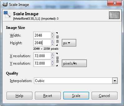
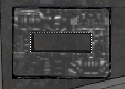
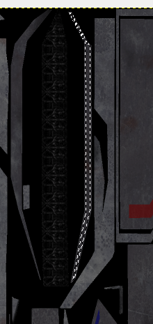
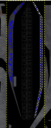
http://casofwar.hard-light.net/images/Metals.rar


Once you get the pack, dig out and open Metalbare0130_3_L.  Open it in a separate by window by just going to File > Open > (your file).  Do NOT open as a layer.  Change the size by selecting Image > Scale.  See below, and note that I clicked on the chain links to unlink our verticle and horizontal. 2048 x 2048.


Copy  our resized metal by selecting Edit > Copy.  Then you can close without saving.  Go back to our main window (where we have the AO and UV).  Paste this as a new layer by selecting Edit > Paste as Layer.

Now in your layers window, you should have 3 images.  The top one should say Clipboard.  Double clicking on the thumbnail for it will bring up Layer Attributes window, and change the name from clipboard to Metal 1.  We will be bringing in another metal later, so be sure to include the number.  Then you can click the thumbnail and drag it to beneath the other two layers.  When finished your layer view should look like mine.


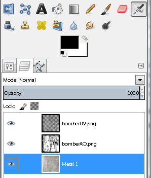
Click on bomberAO so that it is selected.  Then look above our layers. In the above image you can see where it says Mode: Normal, with a drop menu on the same line.  Click the drop menu and change the mode to Multiply.

Now select File > Export, and export to the same folder as where you saved bomberAO and UV.  This should also be where you saved bomberGlass, and where you exported the DAE file from Blender.  Name your current export as bomberText.png.

If you haven’t already done so, download PCS2, the latest version and open it.
https://googledrive.com/host/0B_qLK7VGhoIydUY1RFlzOVNMdGc/pcs2.7z

Once you get it open, select File > Open, and navigate to your DAE from the tutorial.  Then open it.

We aren’t going to get into PCS very much, except to show you how to change and view your textures.

On the left of the image below, you will see many options that we can edit.  Hit the + next to “Textures” to see a list of all textures associated with this model.  There should be 3. 


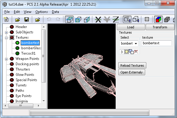
Notice that on the left I have “bombertext” selected, and on the right, in the box under “texture”, it says “bombertext”.  Where mine says bombertext, yours probably says bomberAO, or whatever you saved the texture as.  Change it to read what you just exported your texture as.  Once you do this, simply moving your mouse away from the text box, or hitting enter will lock it in.  Then hit the button that says “Reload Textures”.

Tell me when you get done so that we can continue.   Ha Ha.

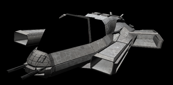
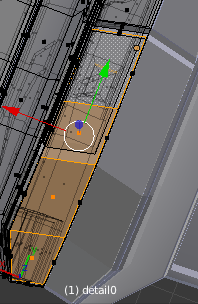
Since you never told me, I’ll continue anyway.  Got some nice metal tuxtures goin on now.  Click where it says “header” to get rid of the selection lines and view the texture.  See below.


Right now you are probably sitting there going “Holy S**t this is so cool”.  I think everyone did when they saw it for the first time.  We did it wrong though.  That was by design.  Notice how we can see the edges of the faces?  Look at the nose if you need clarification.  We should NOT see them.  The reason that we can see them is that we had our UV “on” when we exported the file.  Let’s go back to gimp and do it right.

Notice where we see our layers that next to each layer is an eye?  If you can see the eye then the layer is visible, click the eye for bomberUV.  Notice how our texture changes?  Now export as bomberText.png, and then reload textures in PCS2.  Looks so much better now.


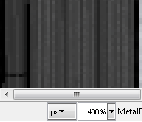
At the lower left of our main window in Gimp, you see some numbers and % (probably 25%).  This is your zoom level.  Hit the arrow next to it for the drop menu and zoom in to 400%.  See below.


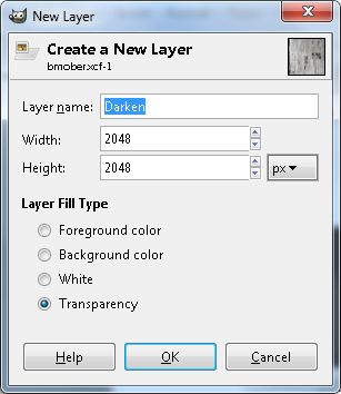
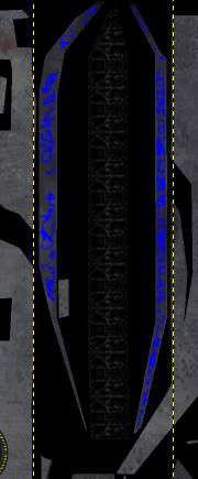
At the top select Layer > New Layer, and the new layer dialogue will open.  Name this layer Darken, and leave it transparent.  See below.


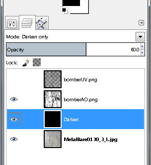
Move Darken to just above Metal 1.  Then select the bucket fill tool in your toolbox, and making sure that Darken is still selected, fill the entire thing with black. Set its mode to Darken Only, and then set Opacity (right under Mode) to 59.  See below for toolbox image of layer placement and settings for Darken.  Notice that I have my UV map shut off. 


Exporting the file now as bomberText.png and reloading textures in PCS2 will show that the ship is darkened, looks much better now.


Let’s play with guns for a moment.  I like my guns to be extremely dark.  Not black, but you get the picture, or will at any rate J.

Scroll all the way to the top and left hand corner.  Remember when we were doing the UV and we placed the guns down the left side of our UV?  Well now we get to mess with them a bit.

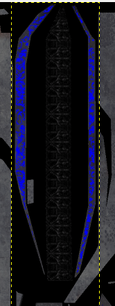
Select the layer called Darken, and create a new Layer called Darken2, and leave it as a transparency.  It should have appeared right above Darken, if not, move it there before continuing. 

Your Layer view should be:

BomberUV - Normal - 100
BomberAO - Multiply - 100
Darken2 - Normal  - 100
Darken - Darken Only - 59
MetalBase - Normal - 100

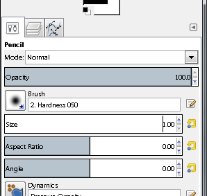
In your tool box, select the pencil.  I used to use the paint brush for this, but found that the pencil works much better.  Directly above Mode in our toolbox, you will find a few tabs.  The one all the way to the left is our tool options, and right next to it is layers dialogue.  Open tool options.  Now set the size to 1.00.  Then go back to layer dialogue.  See below for tool options.


Turn off all of the layers by clicking the eye.  Then turn on UV and Darken2.  Click Darken2 to select that layer if it isn’t already.  This is a very simple process. 

Notice that the block I am pointing to below has a dot in the middle of it.  That is because I clicked it.  Clicking it, and then holding shift before a second click will allow you to create a line between the two points.  So click where you see the arrow pointing in the first image, then Shift click where you see the second image.


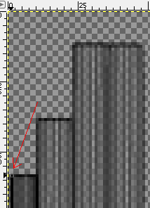
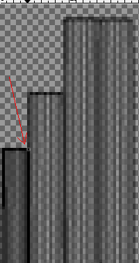
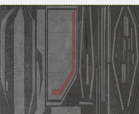
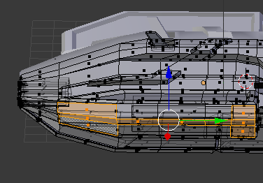
Continue to shift click until you have done the perimeter of what is highlighted below.  Only do the perimeter, but make sure that is done right, as we are creating the border for flood filling.  In the image below, I have zoomed out a bit to show you that we have now traced the perimeter of this UV island.


Now select your Flood Fill (bucket fill) tool and click somewhere within the perimeter of that UV island.  The island should darken, but nothing else should if you’ve done this right.  From this point we call this operation “Border and Fill.”

Border and Fill the rest of the gun UV islands.  They all run down the left side and should be easily discernable.  Two quick hints.  You can include more than one UV island in your perimeter, and if you become unsure as to whether or not you did an island, you can always find out by turning the UV layer off.  Just be sure to turn it back on after looking.
I did the perimeter work and then went back and filled them.  Or you can fill each as you finish, whichever you prefer.  As long as everything is done including the end caps at the bottom.

When you are finished with Border and Fill on the guns, turn off UV and turn on everything else.  Notice turning things on and off does not select the layer, no matter how much you hit an eye, you won’t change layers that way.  It is good to know.

Anyway, with all layers on except for our UV layer, set the mode of Darken2 to Darken Only, with an opacity of 59.

You can export and check it in PCS2.  I do this several times, usually after each step to ensure that I like the finished product.

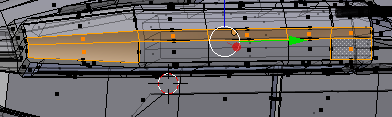
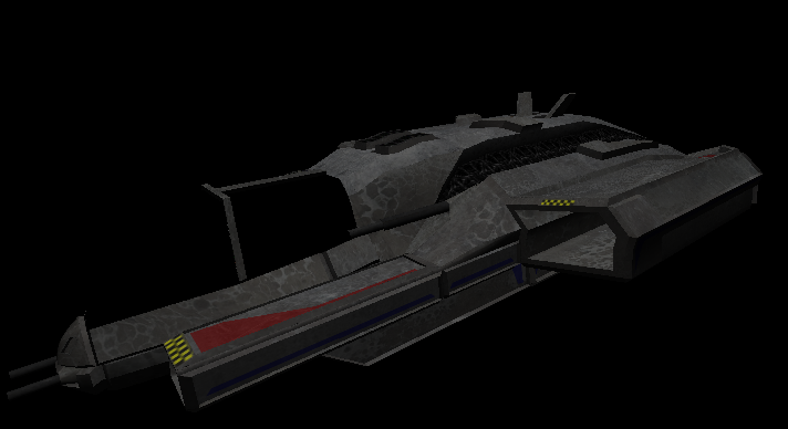
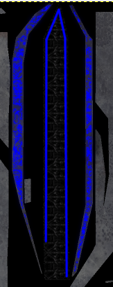
Open our model in Blender.  Then go to UV.  Select the face on the top of the small missile launcher as below.


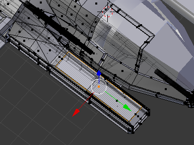
Notice how its counterpart on the UV is highlighted and nothing else is.  See below.


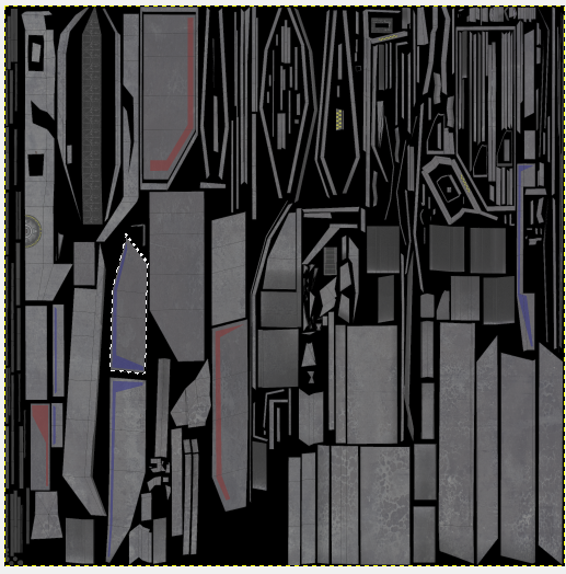
It is a simple matter to find that UV island on our texture in gimp.  Zoom out to 100% to make it easier to find, then zoom into 200% and find it again.

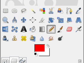
Now in your tool box.  That big black box sitting there, well that is your current color,  click it and then get a nice red.  My box is already red, seen below.


Select Darken2.  Then create a new layer called “Red” and leave it as a transparency.

Your Layer view should be:

BomberUV - Normal - 100
BomberAO - Multiply - 100
Red - Normal - 100
Darken2 - Darken Only  - 59
Darken - Darken Only - 59
MetalBase - Normal - 100

Make sure that Red is selected, and then create something like the following using Border and Fill.  I zoomed out to 100% for the screenshot.


Set opacity to 70.  Then export and see what we think.

I think it’s a little too much, so I am lowering the opacity to 55 and looking again.

Too much and too pink.  So I am moving it to below Darken, and actually raising the opacity to 60.  Try it and look again.

Your Layer view should be:

BomberUV - Normal - 100
BomberAO - Multiply - 100
Darken2 - Darken Only  - 59
Darken - Darken Only - 59
Red - Normal - 60
MetalBase - Normal - 100

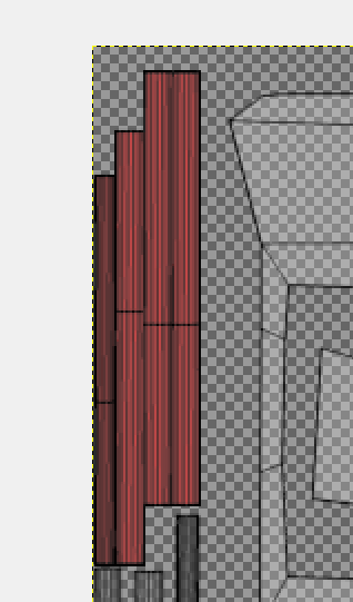
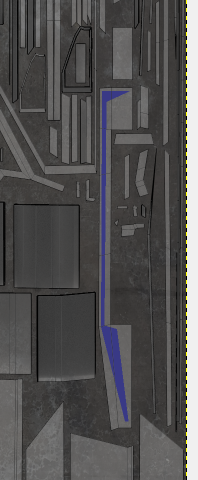
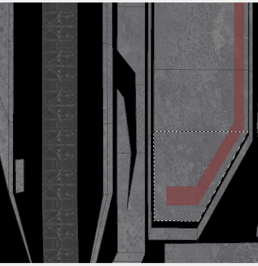
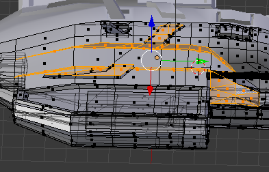
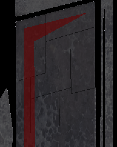
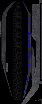
Still too visible for my tastes, but not what I call “anime bright”.  I’ll leave it as a happy medium between my taste and those who prefer the anime bright.  Let’s stay in red for a bit.  Select the top faces of the large missile launcher as below, and then use what is highlighted in the UV to locate the island in our texture.  Remember, when it comes to locating, have UV on.  The only time it should be off is to color check and export.

Once you have it located make something like what you see below using Border and Fill.


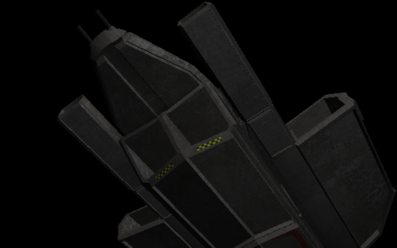
Select the back half of the Bomb bay in Blender, as below, and then find in our texture.


Do something like what you see below.


Kill the UV and take a look.  that’s coming along nicely.

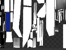
With the Red layer selected, create a new one called “Blue”, and then switch colors to a blue. 

Your Layer view should be:

BomberUV - Normal - 100
BomberAO - Multiply - 100
Darken2 - Darken Only  - 59
Darken - Darken Only - 59
Blue - Normal - 100
Red - Normal - 60
MetalBase - Normal - 100

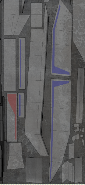
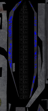
Select the faces below from the side of the large missile bay and locate on the texture.


Paint it like the picture using Border and Fill.  Set opacity to 60. Then kill the UV, export and take a look.


Looks ok.  We’ll leave it.

Your Layer view should be:

BomberUV - Normal - 100
BomberAO - Multiply - 100
Darken2 - Darken Only  - 59
Darken - Darken Only - 59
Blue - Normal - 60
Red - Normal - 60
MetalBase - Normal - 100

In Blender, select the sides of both the small missile launcher and the bomb bay as below.

http://i1283.photobucket.com/albums/a560/ShadowWolf_IH/tut3-23_zpsa3e8bdee.png

Paint some blue on those faces as seen below.


I think that we are done painting, you get the gist of how. 

We are going to add some tech bits next.  There are a number of programs that will let you extract files from the vp’s, and what you do is, you go through the textures there, and you study each one until you find something you like.  Then you extract it.  Then you keep going until you have enough bits to play with.

You take a piece of this one and place it stragetically, and then a piece of that one and place it strategically, and pretty soon you’ve done the tech bits. 

Furtunately for you I am a nice guy, I won’t make you do that yet, instead I have all of the tech bits that you need for this model ready for download.  Simply extract some somewhere that you can easily find them, but NOT in the folder we are using for our model and texture.

http://casofwar.hard-light.net/images/TechBits.rar

Select the following face in Blender, and then find the corresponding face on our texture.


Now Open as Layer “Dock.png”.  Yes navigate to the tech bits I sent you, and open that one as a layer.  This new layer goes under UV and AO, but above everything else.

Your Layer view should be:

BomberUV - Normal - 100
BomberAO - Multiply - 100
Tech Bits - Normal - 100
Darken2 - Darken Only  - 59
Darken - Darken Only - 59
Blue - Normal - 100
Red - Normal - 60
MetalBase - Normal - 100

It is only half the texture, place it as follow.  Once you have it placed, zoom in to 400% and make sure it lines up on the edge of the UV for that face.  See below.


Export and take a look.

Select the four faces shown below, and find them on your Texture.


Now go ahead and grab Beam3.png and Open As Layer.  Open it directly above Tech Bits.

Your Layer view should be:

BomberUV - Normal - 100
BomberAO - Multiply - 100
Tech Bits 2 - Normal - 100
Tech Bits - Normal - 100
Darken2 - Darken Only  - 59
Darken - Darken Only - 59
Blue - Normal - 100
Red - Normal - 60
MetalBase - Normal - 100

Scale Tech Bits 2 by selecting Layer > Scale.  and make it 125 by 125.

Now position it like below. You will need to do this in increments, start at 100%, then 200%, then 400%.  Notice that there is barely any overhang in the upper left corner.  If we wanted to, we could rotate this and set it perfect, but there is no need here.


In your tool box you have a rectangle selection tool, click it, and use it to outline the part of the UV map that we want, keeping overhangs as close as possible.

Select Select > Inverse.  This inverts our selection.  We do this so that we can erase everything else in this layer, without touching the stuff we want to keep.  Follow me?

With things inverted, go to your toolbox and right click the layer called Beam3.  If it is in fact directly above the layer we put our docking ring on, select Merge Down.

Your Layer view should be:

BomberUV - Normal - 100
BomberAO - Multiply - 100
Tech Bits - Normal - 100
Darken2 - Darken Only  - 59
Darken - Darken Only - 59
Blue - Normal - 100
Red - Normal - 60
MetalBase - Normal - 100

Use your eraser tool to erase our tech bits until you have something like below.  You will need to resize it, but I taught you how.  I set mine on about 5.


Now select the inner box using your rectangle select, and then erase it.  See below.


Select Select > None.

Shut UV off, export, and take a look.  Not bad but a little too bright.  Let’s darken it.  Make sure that our tech bits layer is selected, and then use your rectangle selected tool to select our tech bit.  Grab your brush, and change the color to black.  Under tool options set the opacity to 27, size 15..  Go over the entirety of our box a few times, but over the outside portion about 6 times.  See below for finished.

http://i1283.photobucket.com/albums/a560/ShadowWolf_IH/tut3-31_zps0f4f9db0.png

That darkened things up nicely.  Don’t forget to Select > None before exporting.  Now when we darken the greeble walls it will look pretty nice.

We have our tech on one layer, but you don’t have to, You can put each one on a separate layer.  In order to erase though and not leave behind a white box, you need to merge with a transparent layer first, which is what we did.  You can darken each piece individually the way we did, you can play with the opacity of some paint stuff to make it look faded, you can darken some areas of paint to make it look “abused”.  Possibilities are limitted by only by imagination.

I am just going to add a bunch of tech stuff now, and then show you some images.  You know how to add them, all of the lessons are held in here.  I will tell you any “special” things that I did. 

Arbitrary Rotation.  If you go to Layers > Transform, one of your options is Arbitrary Rotation.  Open something as a layer, and go into Arbitrary Rotation.  You’ll have it figured out in no time.

Break the chain to scale on one axis instead of both.

Use opacity settings on the new mayer before merging.

Use your lasso to surround an area that you want to paint without painting anything else (or darkening).

When you are done with these, come back here, we’ll have some more fun with grunging things up a bit,  and then with Glow maps, Shine, Normal, -trans, maps.  We still have a good amount to do before we are finished with our texture.


Once I got the canyon tech placed, which was actually one piece scaled down, and then Layers > Duplicate and move the layer, I went over it with a paint brush size 50, then I went over the outside edge one more time.  Basically I kept the border of the tech about halfway into the brush (circle).

Other than that it was pretty strightforward, simply use the lessons that you learned above. 

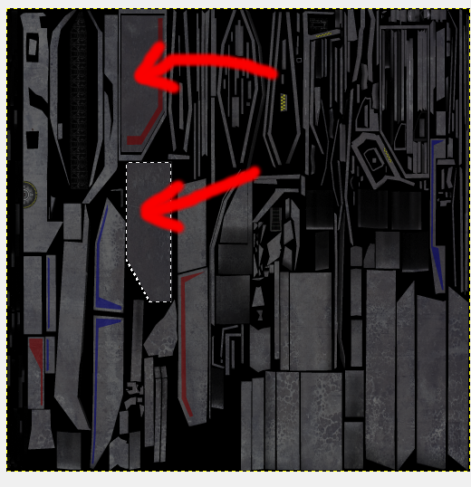
It is taking shape, but we have work to do.  Currently it looks like it has been stamped out of one pice of metal, which it has.  We need to defeat this, but first, I don’t much care for the color of the metal.  So, click on our Metal1 layer, and then select Layer > New Layer.  Call it Gunmetal Bluing, and it doesn’t matter what fill color we use (mine was still on transparency).

Your Layer view should be:

BomberUV - Normal - 100
BomberAO - Multiply - 100
Tech Bits 2 - Normal - 100
Darken2 - Darken Only  - 59
Darken - Darken Only - 59
Blue - Normal - 100
Red - Normal - 60
Gunmetal Bluing - Normal - 100
MetalBase - Normal - 100

The new layer should be directly above your metal base.  Change colors and get a nice royal blue.  Then bucket fill after making sure that Gunmetal Bluing is the selected layer.  Set the blend mode of the layer to “Color”, and the opacity to 7.

I like that bunch better, the difference is subtle, but very cool.  That’s a pretty good lesson, subtle is a good thing.

File > Open Metalbare0130_5_L.  This will open in a separate window.  Resize it to 2048 x 2048.  Edit > Copy.  Then you can close that window, and in our main texture window,  Edit > Paste As > Layer.  Then move the new metal layer all the way to the bottom.  Kick up UV, we will need it turned on.

Your Layer view should be:

BomberUV - Normal - 100
BomberAO - Multiply - 100
Tech Bits 2 - Normal - 100
Darken2 - Darken Only  - 59
Darken - Darken Only - 59
Blue - Color - 7
Red - Normal - 60
Gunmetal Bluing - Normal - 100
MetalBase - Normal - 100
Metal2 - Normal - 100

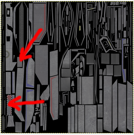
What we are going to do now is take care of the “stamped from one piece of metal” look.  We do this by erasing our metal base in strategic areas to let a different metal base shine through.  I hope that sums up what we are about to do.

With the bottom layer (Rename it to Metal 2) selected, create a new layer, this layer need not be named, but does need to be transparent.  Once it is created, merge MetalBase with it.  Name this new layer Metal 1.

Use your Lasso select tool to select the area outlined below.  Then hit Delete. And don’t worry about the area on mine being black, I’ll get you there.


Notice how it went away?  Select > None and then take a look in PCS2.  That’s all there is to it.  Stay with me while we do some more.

Looks pretty good, but I think it is too bright.  Change the color to black in your color selector.  With Metal 2 selected create a new layer, filled with Foreground color.  Name the layer Black.  Set opacity to 26, and mode to Darken. 

Your Layer view should be:

BomberUV - Normal - 100
BomberAO - Multiply - 100
Tech Bits 2 - Normal - 100
Darken2 - Darken Only  - 59
Darken - Darken Only - 59
Blue - Color - 7
Red - Normal - 60
Gunmetal Bluing - Normal - 100
MetalBase - Normal - 100
Black - Darken - 26
Metal2 - Normal - 100

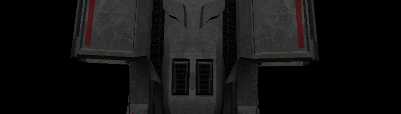
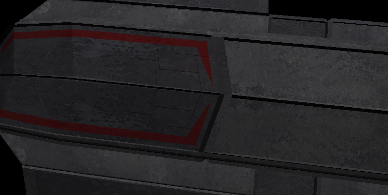
Now export and take a look in PCS2.  That looks better.  Go ahead and do the rest of that section...ie the top of the large missile bay.  All of the flats.  Do the bottom as well.  See below.


Now get the following sections of the small missile bay. 


We’ll only do a few more in this tutorial, but what you are wanting to achieve here is simply breaking up the model.  It adds a splash of color, even if it is simply a different shade.  You get the picture.  Keep thing flowing with the lines of the model.

Get the pieces that you see highlighted in the next two images.


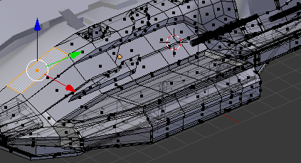
Select the canyon walls, the tops of the greebles shown, and the outside of the fuselage near the gun mount.  See below.


You know what to do.  Normally I would do more than this with it.  Normally I would use 3 metal textures.  The thing about using 3 is, go over the model deleting in strategic places like we’ve been doing, but delete from the top TWO metals.  Then go back over the model and delete from only the top  metal in other places.  You understand, in some places you want the bottom texture to show through, in others the middle, and in others the top. 

If you want the bottom metal to show through, make your selection, delete from the top metal layer, then switch to the middle layer and delete from it. 

If you want the middle metal layer to show, only delete from the top metal layer.

At this stage I usually darken my greeble walls.  We aren’t going to because it is a pain.  It is worth it on a model for release, the darkened walls add depth.  It is really easy, use your lasso to make your selection, then use the brush painting black.  Brush options are either Darken or Normal, with your opacity of the brush set to your liking. 

As long as we are discussing “to your liking”, remember that all of the Opacity settings in this tutorial are to MY liking.  Change them to what YOU like when you do your own model. 

Before you start deleting from the metal layers, take a look at what you have.  The large panels are boring and lackluster.  We could have gone with some smaller panels.  To do this, simply create a transparent layer under the UV, and draw on it with a black Pencil.  Making smaller panels inside the larger ones. 

Your Layer view should be:

BomberUV - Normal - 100
BomberAO - Multiply - 100
Tech Bits 2 - Normal - 100
Darken2 - Darken Only  - 59
Darken - Darken Only - 59
Blue - Color - 7
Red - Normal - 60
Gunmetal Bluing - Normal - 100
Lines - Normal - 100
MetalBase - Normal - 100
Black - Darken - 26
Metal2 - Normal - 100

Even though we didn’t do this (mostly because I forgot until it was far too late), I will show you what I mean in the images below.  Before and after.


What I did was use the pencil tool color black, and in tool options made it size 1.00, Mode normal, hardness 2, opacity 100.  Create a transparent layer called Lines just beneath the UV layer, and draw the lines on it.  Then move Lines to just above my top metal.  Set the opacity of the layer to 50.  Done.

Your Layer view should be:

BomberUV - Normal - 100
BomberAO - Multiply - 100
Tech Bits 2 - Normal - 100
Darken2 - Darken Only  - 59
Darken - Darken Only - 59
Blue - Color - 7
Red - Normal - 60
Gunmetal Bluing - Normal - 100
Lines - Normal - 50
MetalBase - Normal - 100
Black - Darken - 26
Metal2 - Normal - 100

You want UV on for that so that you can trace any of the lines on the UV where things remain flat.  Don’t trace lines where panels come together in a 3 dimensional angle.


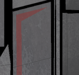
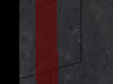
If you look really close, you can see a line drawn in the red.  It was actually drawn in black, but because we put Lines beneath everything except our metal layers, any paint will show on the line, making it appear to have been painted. 

Remember that these lines offer a great deal of versatility for changing which metal is shown. 

Something else that you can do is create some rivets.  A simple black dot is all it takes.


I created a transparent layer called Rivets and then used a paintbrush size 1.00, hardness 2, mode normal, opacity 100, angle 22.  If you opt for rivets, remember to only put them on one side of a “seam”. 

Your Layer view should be:

BomberUV - Normal - 100
BomberAO - Multiply - 100
Tech Bits 2 - Normal - 100
Darken2 - Darken Only  - 59
Darken - Darken Only - 59
Blue - Color - 7
Red - Normal - 60
Gunmetal Bluing - Normal - 100
Rivets - Normal - 100 **optional**
Lines - Normal - 50 **optional**
MetalBase - Normal - 100
Black - Darken - 26
Metal2 - Normal - 100
 
Let’s dirty things up a bit. 

Create a new transparent layer called Grime1.  Place it above Tech Bits.  Mode should be Multiply, opacity 50.

Your Layer view should be:

BomberUV - Normal - 100
BomberAO - Multiply - 100
Grime1 - Multiply - 50
Tech Bits 2 - Normal - 100
Darken2 - Darken Only  - 59
Darken - Darken Only - 59
Blue - Color - 7
Red - Normal - 60
Gunmetal Bluing - Normal - 100
Rivets - Normal - 100 **optional**
Lines - Normal - 50 **optional**
MetalBase - Normal - 100
Black - Darken - 26
Metal2 - Normal - 100

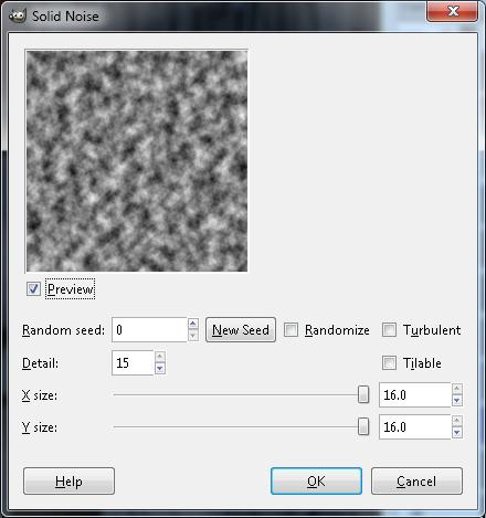
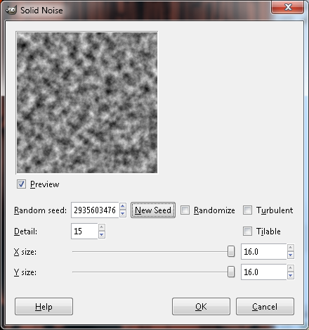
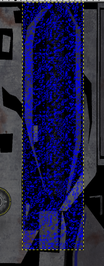
With Grime1 selected, select Filters > Render > Clouds > Solid Noise.  When the dialogue comes up. make your settings as below, and hit OK.


Select Color > Brightness and Contrast.  Set Brightness to -90, and Contrast to 90.

Now select Color > Invert.  Then select Color > Color to Alpha.  It should still be white, if so hit ok.  If not, make it white, then hit ok.

Now select Filters > Blur > Motion Blur.  You can adjust these settings to taste, but for the purposes of this tutorial, set it at Linear, Length = 47, Angle = 89.  Angle 0 will give you a horizontal smear, so angle 90 gives a straight up and down one.  Since most of our texture is “verticle”, we will go with a 90.

Some rust will be a bit harder, but not much.  Select Tech Bits, and create a new transparent layer called Rust.  Set the mode to Screen and the opacity to 50.

Your Layer view should be:

BomberUV - Normal - 100
BomberAO - Multiply - 100
Grime1 - Multiply - 50
Rust - Screen - 50
Tech Bits 2 - Normal - 100
Darken2 - Darken Only  - 59
Darken - Darken Only - 59
Blue - Color - 7
Red - Normal - 60
Gunmetal Bluing - Normal - 100
Rivets - Normal - 100 **optional**
Lines - Normal - 50 **optional**
MetalBase - Normal - 100
Black - Darken - 26
Metal2 - Normal - 100

Switch to a nice rust color, I am using html notation b32d00, and flood fill the layer using your bucket.

Select Tech Bits again and create a new transparent layer called Noise.   

Your Layer view should be:

BomberUV - Normal - 100
BomberAO - Multiply - 100
Grime1 - Multiply - 50
Rust - Multiply - 50
Noise - Normal - 100
Tech Bits 2 - Normal - 100
Darken2 - Darken Only  - 59
Darken - Darken Only - 59
Blue - Color - 7
Red - Normal - 60
Gunmetal Bluing - Normal - 100
Rivets - Normal - 100 **optional**
Lines - Normal - 50 **optional**
MetalBase - Normal - 100
Black - Darken - 26
Metal2 - Normal - 100

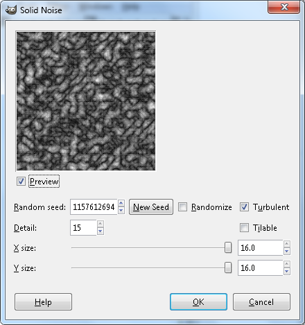
With Noise selected, select Filters > Render > Clouds > Solid noise, and use the following as your guide for the settings.


Once it renders the clouds, turn everything off except for the layers named “Noise” and “Black.”

Select Colors > Brightness and Contrast.  Set Brightness to -96, and Contrast to 99.  You can really see the difference in this, so adjusting them will grow or shrink your rust areas.  For what it’s worth, this also works for our grime layer.

With Noise selected, Edit > Copy, and then turn on everything except for UV.  Then turn off Noise.

Select the layer called Rust, and select Layer > Mask > Add Layer Mask.  When the dialogue pops up make sure that White (full opacity) is selected and hit Add.

Next to our Rust thumbnail is a white box.  Click it.  Now click the Rust thumbnail.  You are switching between the layer and the mask.  Whichever is inactive has a black outline, the active one has a white outline.  So select the mask, and then hit CTRL V to paste, and CTRL H to anchor it.

Your Layer view should be:

BomberUV - Normal - 100
BomberAO - Multiply - 100
Grime1 - Multiply - 50
Rust - Multiply - 50
Noise - Normal - 100 ** off **
Tech Bits 2 - Normal - 100
Darken2 - Darken Only  - 59
Darken - Darken Only - 59
Blue - Color - 7
Red - Normal - 60
Gunmetal Bluing - Normal - 100
Rivets - Normal - 100 **optional**
Lines - Normal - 50 **optional**
MetalBase - Normal - 100
Black - Darken - 26
Metal2 - Normal - 100

Currently we have rust on our canyon floor, and I don’t want it there.  Select the mask, and then use your lasso tool to outline the tech in question.  See below.


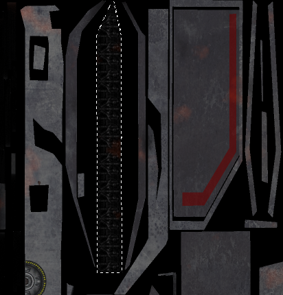
Hit delete.  Switch from the mask to the layer, and hit delete a second time.   When you delete on the mask, you are deleting the cloud cover, when you delete on the layer, you are deleting the color.

Switch the color selector to Black or White, either one.  Select your AO layer, and then use your bucket flood fill on it.  Choose somewhere outside of all of the islands.

The Grime and Rust are adaptations of what Scooby does.  He does other things that we can’t do with our model due to the mirror modifier.  To see how he does things and get some more tips visit http://www.hard-light.net/forums/index.php?topic=43189.20

You can delete Noise.  We are done with our base texture.


3.2 Glow Maps

Glow Maps are easy.  They give us some lighting effects on our model, and can do some pretty cool stuff.

For now, you can save your bomber.xcf in gimp and close it.  Then open bombertext.png.  Make a new layer called Glow.  Make it black, or flood fill it black, what ever you want to do. 

Your layer view should be:

Glow - Normal - 100
bombertext - Normal - 100

Turn Glow off.

Open a new image, by selecting File > New.  Make it 512 x 512.  Now add some noise by selecting Filters > Render > Clouds > Solid noise.  Make it like the image below. 


Let’s create some extreme lightning by selecting Colors > Invert.

Now select Colors > Threshold, and make your settings 128 and 153.  Hit OK.

Create a transparent layer called Blue, and then flood fill it with Royal Blue.  Then give it a mask by selecting Layer > Mask > Add Mask.  In the add mask dialogue, select Black (Full Transparency).  Then copy our noise layer and paste it into the mask.  Don’t forget to anchor it.

Delete the noise layer, and Duplicate Blue by selecteing Layer > Duplicate Layer.

We need to blur the bottom one now.  Make sure that you have the mask in Blue selected, and select Filters > Blur > Gaussian Blur, set it to 20 and 20.

Select Edit > Copy Visible.  This is important because copy will only give you the layer, or selection.  Copy Visible is what we need here.  Then go back to our main work window and select Edit > Paste As > New Layer.

Duplicate the layer and then use your move tool to move the duplicate until it becomes an extension off the bottom of the original layer.  Change original to Blue 1, and merge the duplicate down by by right clicking on the duplicate layer and selecting Merge Down.

The layer was too short for our needs, so we lengthened it by Duplicating, moving and merging.  Duplicate the finished product and name the Duplicate Blue2.  Then turn Both Blue Layers off.

Using your Lasso tool, select an area like the one below.  Notice that I am INSIDE the edges of the island.  I used a zoom of 400 for this. 


Turn on Blue 1, make sure that it is selected.  Then invert our selection by selecting Select > Invert.  Then hit delete.  See below.


Now let’s do our other canyon wall.  Make your selection using lasso.  Turn on Blue 2, Select Blue 2, Invert selection, and hit delete.


Now merge Blue 2 Down into Blue 1.

If you want to see how it looks, turn on Glow, and then export as bomberText-glow.png.  Take a look in pcs2.

When you get back, go into your secondary work window.  The one where we built the Blue layers with masks.  Select Image > Scale, and change it to 256 x 256.  Copy visible.

In your primary work window, paste as a new layer.  Move the layer so that it spans across both canyon walls.  Then duplicate it and move the new layer down, in essence lengthening the original.  Keep duplicating until and moving until both canyon walls are covered, then start at the the top and merge them down until there is only one new layer.  Name it Blue 2.  See below.


Duplicate the layer and name it Blue 3.  Turn Blue 2 and Blue 3 off, then use your lasso and make a selection like below.


Turn on Blue 2, and make sure that Blue 2 is selected.  Invert the selection by selecting Select > Invert, then hit delete, then Select > None.   See below.


 You already know that we are going to do the other canyon wall and Blue 3.  I don’t think I need to walk you through it.  Make it happen.  See below.


Merge Blue 3 down into Blue 2.  Then duplicate Blue 2 and call the duplicate Blue 3.  With Blue 3 selected, select Filters > Blur > Gaussian Blur.  Set it at 20.  Merge Blue 3 down when finished.

Create a new transparent layer called Blue 3.  Set your paint brush size to 10, and draw the following lines on the canyon floor.


Guassian Blur Blue 3 at 20.  Set the Mode to Normal, Opacity 10.  Then Merge it down into Blue 2, and Merge Blue 2 down into Blue 1.  See below.


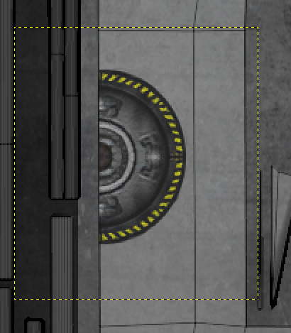
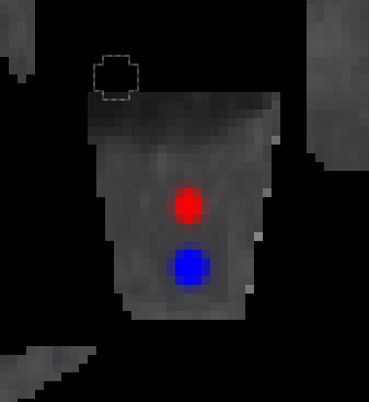
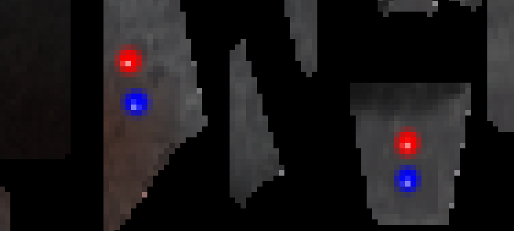
Select the face that you see selected below.  Then find it on the UV.  It is small, so you will have to zoom in to find it.  Hint, it is in the center.  NOw find it in our Glow map window.

I went ahead and zoomed in to 800 for this one.  Most times I will work in the same XCF that I used building the base texture.  It allows you to have the UV map up, which helps.

Mkae sure that your Blue layer is selected, and use a paint brush with size set at 7.  See below for what to do.  In order to get it as dark as what you see below.  You need click 5 times in each color.


Looks pretty good, but we are about to make it look better.  Change your brush color to white,  size 1, opacity 75, and click 3 times for one pixel in red, and 3 times for 1 pixel in blue.  See below.


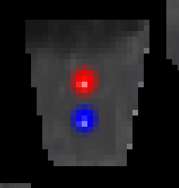
Zoom out to 200%, looks good.

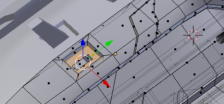
Select the following face of the model in Blender.  Then find it on the texture.


Follow the exact same procedure as above to make the image below.  Of course it is sen in relation to what we just did.


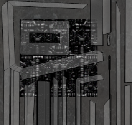
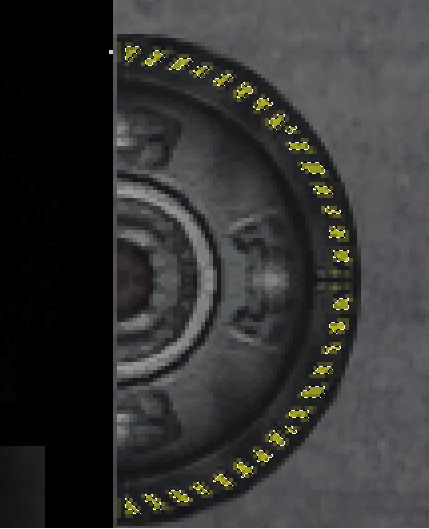
Move over to your dock tech, and then select Select > By Color, and click any of the yellow, then shift click to keep selecting the different shades.  Shift select until your selection is comparable to below.


Edit > Copy, then switch to Blue 1, and simply CTRL V to paste, and CTRL H to anchor it. Turn Glow on and zoom out to about 50.

Notice that we also got the checkerboard patterns that we put on the front of our missile / bomb bays.  We could leave it, but then it would look too new a dirty and somewhat rusted bomber.  So simply erase them.

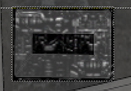
Turn on Glow, export as bombertext-glow.png, and take a look.  We are done with the glow map.
« Last Edit: May 11, 2013, 06:37:05 pm by ShadowWolf_IH »
You can't take the sky from me.  Can't take that from me.

Casualties of War


Offline ShadowWolf_IH

  • A Real POF Guy
  • 211
    • CoW
Re: A complete FS ship tutorial -- EXTREMELY IMAGE HEAVY
3.3 Shine Map

Shine maps are actually pretty easy.  Almost as easy as glow maps.  Think about things that we don’t want to be shiny on our model.  We have grease smears and rust, those definately won’t be shiny.  We have glow maps, they glow, they don’t reflect. Paint shouldn’t be reflective either, unless you want it to look like reflective tape, which I don’t.

Since this is my first ever Shine map, you will get the basics.  It is up to you to experiment with this stuff and find what YOU like.  So let’s get started.

First Open the xcf file for our diffuse texture in gimp.  Unlike your PNG’s or TGA’s, the xcf holds all of the layers. So we need it open now.

Turn on all layers.  Then turn off BomberUV, Grime1, and Rust.  Select Edit > Copy Visible.  Then select Edit > Paste As > New Image.

Now in our new image, which we will refer to as Shine, as oposed to XCF, change “Pasted Layer” name to “Base.”  Because we were dealing transparencies at our source, our copy should have an Alpha channel.  We need to make sure though.  With Base selected, select Layers > Transparency.  If you can select “Add Alpha Channel”please do so.  If you cannot, it is because there is already an Alpha Channel in the image.

Either way we now have an Alpha Channel.  So we need to add a Layer Mask.  Select  Layer > Mask > Add Layer Mask.  Then in the dialogue that pops up select “Transfer layer’s alpha channel”.  Hit Add.

We can now edit the Alpha channel.  So, click on the Mask to select it (there should be a White Box around it if it is the active selection), then use your bucket tool to flood the work area with Black (HTML Notation 000000).   

You should now be seeing the gray and white checkers of transparency in your work area, but notice in layer view that the mask is black. 

Export this as bombertext-shine.tga.  Take alook in PCS2. 

We now have a working Shine map.  Wipe off that silly grin, we have more work to do.

Right click on the layer and select “Disable Layer Mask”.  Now we can see what we are doing. 

For starters, it is far too shiny.  We have rust and grime and a show room shine.  Doesn’t look natural.  Be sure that our layer is selected, not the mask, and select  Colors > Brightness and  Contrast and make your settings as below.


Right click on the layer again and enable the mask by again selecting Disable Mask.  Then export it as the same name as before, and take a look.  Not as shiny now.  That is how you adjust the shine level.

We actually did a few things here.  By adjusting the Brightness we adjusted the amount of shine.  By adjusting the contrast, we added a good deal of black, thus adjusting which areas shine.  Undo a few times until you have undone Brightness and Contrast.  Make sure that Base is selected, then adjust only Brightness to -45.

See how much shinier it is now?  In all actuality, it is no shinier than it was before, but we didn’t adjust the contrast, so in this iteration, the entire map is shiny.  Make sense?

I want the entire map to be shiny, but not as shiny as it is.  Undo a couple times again to undo the Brightness and Contrast, then set Brightness to -127.  With this done, do it again.  Brightness and Contrast, Brightness to -127. That looks like the amount of shine that I want.

Remember how we blued everything a bit with the layer called Gunmetal Blueing?  Well I want that to come through a bit in the Shine.  Not too much, but a little.  to do this select Colors > Hue-Saturation, and make your settings as below.  You can play with these options to find what they do and what you want, but when you are done, set them as below.


Export and take a look.

Let’s play with environmental reflections a bit.  Select the mask, and then select Colors > Brightness and Contrast, and make your settings as below.


There is no sense in looking at the moment, as there is no environment to reflect.  Again, these are just the settings that I wanted on this particular machine.  When you do it for you, the settings are for you to experiment with and set.

Switch tpo XCF, and again Copy Visible.  Switch to Shine, and paste as a layer.  Make sure that your new layer is selected, it is called “Clipboard” by the way.  Duplicate this layer and then turn the duplicate off.  Select Clipboard.

Make sure that your color is Black, and then Bucket fill in the work area.  Make sure that you click an area that is already black.  Unless you are paying attention, you won’t see a change, but if you are watching our “long tech bit”, you will see the change.

Zoom in on the small tech piece seen below.


Bucket fill the surrounding gray until it looks like the image below.


Now duplicate the layer.  The new layer will be named Clipboard Copy #1.  Set it’s mode to Screen, then right click it and Merge Down.  See how the gray in the tech bit is brighter?

Do it again.  Duplicate, set the mode to Screen, then Merge Down.  The gray should be nearly white now.

Use your Rectangle Select Tool to select the following area.


Select Base Layer, not Mask, and paste then anchor using CTRL V then CTRL H.

Reselect the tech bit in Clipboard.  Then Paste and Anchor it in the Mask.

With Clipboard selected, use Lasso Select Tool to select the large piece of tech seen below.


Do the same thing you just did, copy, then switch to Base layer and paste and anchor, then do the same for the mask.

When you look at it in PCS2, notice how much shinier the tech bit is than the rest of the craft?  That is because of how light it is in comparisson.  The craft is dark, so not much shine,the tech is light, so lots of shine.   

Believe it or not,the hard part is done.

Switch to XCF and turn off all layers.  Then turn on Grime and Rust.

Copy Visible and then paste it as a new layer in Shine.  Layer order doesn’t matter. 

Zoom out to about 50.  Now select Select > By Color.  Click a rust spot, you should see all of the rust spots get selected.  Then Shift click a grease spot.  Now all of the rust and the grime should be selected.

Disable the mask, and you should see where some of our selections are being intrusive on our tech bits. This will not do.  See below.


The two selected areas that I have arrows pointing to are going to interfere with the shine our chrome pieces.  Erase them but first make sure that your Grime/Rust layer is selected.  Select Select > None.

Now reslect by color, for both rust and grime.  Best way is to turn off Base, and then make sure that you have Rust/Grime layer selected.  Once you have the selections by color, turn Base back on and notice that the offending selections are gone.  Turn off Rust/Grime layer.

Select Base layer, and then use black to flood fill inside one of the circles (selections).  Then enable the Mask, select tghe Mask, and do the same thing.  Finally, select Select > None.

With this done, take a look at it.  Notice how hard the edges between the shiny areas and the  grease/rust areas?  Looks like a sticker.  We don’t want that.  See below for an example.


So select the Base Layer, and then select Filters > Blur > Selective Gaussian Blur.  See below for settings.


Once it completes, select the Mask, and blur it in the same manner, same settings.

Now Open as layers, and navigate to your Glow map.  Currently in your layer view, the only layers that should be turned on are your Glow map and Base.

Select by color and keep using shift select until all of the blue is selected as in the image below.


Then keep using shift select to select all of the Yellow.  Use shift select because we want it in addition to the Blue.  Then shift select the Red.  In this manner, everything in the glow map except the black selected.  When you do the red, don’t forget to the get the white dot in the blue lights on the gun mounts.

Turn off the Glow map and select Base layer.  Hit delete, then select the mask, and hit delete.

There should still be an untouched copy of your diffuse texture sitting as a layer.  Turn it on.

Use color select to select both red and blue, then select Base and hit delete, then select the mask and hit delete.

That’s it, we are done with the shine map.  Although not perfect and I’ll wager not even 100% correct on the best way to do things, you can and will get a shine map onto your ship by following these steps.

Remember, I am just beginning with these, as such there is a wealth of information out there yet to pour through.  These two threads should help with a good deal of this.

The Gimp Thread

Figuring out ship shininess

3.4 Normal Maps

Once again this is a first for me.  Haven’t made a Normal Map before, so this will just be a basic procedures tutorial.

Go here and get the plug in.

Normal Map plugin for Gimp

Before we do Normal Maps, know that at the time of this writing PCS2 does not display Normal Maps.  So while I am including this texture types in this section, you will probably want to skip this section for now and go straight into PCS2 and Tabling. Then come back here to learn this.  Alternatively, you could look ahead and learn just enough to get your ship into Freespace2, just for viewing purposes.  Either way, once you get it into FreeSpace2, you can either view it in the Tech Lab, or in Fred. I view mine in Fred.

So let’s make a Normal Map.

Step 1 is the height map.

We’ll be working in the XCF. Get it open.

Select the layer named “Red” and create a new layer above it.  Call the  new layer “Gray”.  Doesn’t matter what you fill it with. Then turn off everything ABOVE this layer except for BomberUV.

Select the very top layer, and create a new transparent layer called Blue Lines. Draw something like the blue lines shown below.   It doesn’t have to be exact.  Draw them in blue.  When we are finished, everything in Blue will be recessed, everything in Red will be raised up, and everything else will be neutral.


When you are finished, create a new transparent called RedLines.  Draw something like the what you see below.


Turn on the layer called Tech Bits.  Locate the tech bit that looksllike the image below. With Blue Lines selected, color the areas in blue.


Now on Red Lines, paint red as below.


Finally, put what you have just done together to create something like the following. The darkest areas get colored in Blue, the lightest in Red.  Leave the rest.


Shut everything off except for Red Lines, Blue Lines, and Gray.  See below.


Copy Visible and then Paste as a new image.

In the new Image,select by color and choose your Blue coloring.  Then go to flood fill and fill it in black.

Select by color again and select Red this time.Fill it in White. See below.


Select Filters > Map > Normal Map.  The top option is Filter, I set mine to 5x5.  Then hit ok.

When it gets done, you have the bluish purple Normal Map.  Now select Colors > Components > Decompose.  When the dialogue box opens change Color Model to RBGA.

This opens in a new window,with four layers.Red, Green, Blue, and Alpha.  Select Red and copy it. Paste it into Alpha.  Then Copy Green, Paste it into both Red and Blue.  Don’t forget to anchor.

Then simply Color > Components > Compose.  Once again Color Model is RGBA. It willcompose in a new window. Export as bombertext-normal.tga.

We are done with Normal Maps.

3.5 -trans

Trans maps are very very cool, and not just because of the simplicity to create.  The thing is how much they add to a ship.  We will only be doing our cockpit glass in one.

While building the cockpit model, two things happened that have screwy effects on this map.  One I foresaw, and left it alone as a lesson, the other I did not.  When you look at the image below, notice the black lines on the cockpit.  Had we not smoothed the cockpit glass, this would have happened.  This is where the hard edges of the glass meet, and it messes with the trans map.  Low poly and not smoothing caused this. 


I didn’t foresee that.  That got caught and fixed before writing this.  Just wanted to bring it to your attention here.

So, open Gimp and grab BomberGlassUV.png.

This is very easy.  Change your color to White (ffffff), and then Shift Bucket fill the work area.

Add a Layer Mask (transfer Alpha) and flood it with Gray (808080).

Set the opacity to 40%.

Export it as BomberGlass-trans.tga.

Don’t bother looking yet, you won’t see it.

Copy Visible and Paste as a new image.  This new image will be the shine map for the cockpit glass.

Add a Layer Mask (transfer Alpha) bucket fill it White (ffffff).

Select the layer base (not mask) and bucket fill it in Black (000000).

Export as BomberGlass-trans-shine.tga.

Open the model in PCS2 if it isn’t already open,  go to the textures section, and tell PCS2 to use BomberGlass-trans.

We are done.  If you know how to get your ship into FS2, you can see it in Fred.

As you rotate the ship, you may notice a centerline in the cockpit.  I saw this coming but left it as a lesson.  When you do your cockpit glass, apply the mirror modifier BEFORE you UV it.  I don't think it needs any further exlpanation.

The last thing that I do is open Paint.net, get it at http://www.getpaint.net/.

Open all of the textures and turn them into dds files with DXT5 compression.  Delve into the different uses of the different dxt variables, I haven't yet, but knowing that some tihngs must be in dxt5, I just do them all that way.
We are done with texturing.


« Last Edit: May 24, 2013, 09:06:09 pm by ShadowWolf_IH »
You can't take the sky from me.  Can't take that from me.

Casualties of War


Offline ShadowWolf_IH

  • A Real POF Guy
  • 211
    • CoW
Re: A complete FS ship tutorial -- EXTREMELY IMAGE HEAVY
4.0 PCS

PCS2 is where we turn our model into a ship in the game.  We add weapons, subsystems, docking points, and several other things.  This is where it happens.

4.0a PCS

Now, open your model with PCS2. You'll need a recent (at least 2011, but the more recent the better) version of the program. You should be seeing something like this:


First, check in the Textures tab if nothing weird did make it through export - you should only be seeing textures of which you know where they are used. Now, it may be most convenient to switch to ortographic mode - it's in the button bar at the top.
If you have difficulty following the next part, I suggest that you open up a fighter/bomber from the MediaVPs, and see how it's done there. Seeing it for yourself tends to work better than pictures.

Next, go to Weapon Points - here, you define where the guns and missile ports are. Select Gun Points, and add your first gun bank: in the Bank section on the panel to the right, press the New button (the yellowish square). Now, add gunpoints to this bank - the number of gunpoints will define the number of guns in that bank. Press the New button in the Point section. If you now go to wireframe mode (it's in the button bar at the top), you should be able to see a small sphere with a line sticking out of it. Well, the sphere is the place of the gun, the line is the direction it will fire. Edit the gunpoint's coordinates (the three numbers under Point, not under Normal) until it's at the right spot. FS uses a nonstandard axis convention: X is positive to the port of your ship, Y is positive upward and Z is positive forward. If you have one point, you can make the one on the other side by duplicating it (next to the New button) and changing the sign of the X-coordinate.
Set up missile banks the same way - note that the number of firepoints does not determine the number of missiles.

Next up, docking points. A fighter generally only needs one, for rearming purposes. So select the tab, then on the panel on the right click the topmost New button. Press the down arrow next to the Properties textbox and select the entry, then rename the point from "Docking Point" to "rearming dock". Skip the Paths section, we'll take care of that later.
Now here's the knack: each docking point actually has two points. The dockee ship will dock in the middle of them. Point 1 should be the most forward one (unless you want the support ship to dock backwards).
So press the downmost New button and edit the coordinates until it's in the right place. Then, adjust the Normal vector until it's approximately perpendicular to your ship's surface, and press the Norm button next to it. The normal coordinates work in pretty much the same way as the other coordinates; 0:1:0 has the vector pointing straight up. Then duplicate the point and move it back a little.

Thrusters: these points define where the thruster plumes will be, and in which direction they'll fire. Thrusters are organised in banks, each corresponding to one of the engine subsystems (mainly relevant for capships); if one engine is disabled, the corresponding thrusters will cut off. Press the topmost New button, and under Properties, associate this bank to the default Engine subsystem (which we'll add in a minute).
Now under Glow Points, make a new one and set its radius to something you can see. Then move it to the right place. The normal is set pointing straight back by default (0:0:-1). Add more points as needed - a fighter/bomber generally has only one engine system, so all thrusters can be in the same bank.

Glowpoints: You know how most of the MediaVP Terran ships have these little (sometimes even blinking) lights on them? The Orion is a good example. Well, those lights are defined with glowpoints. These too are organized in banks, much like the thrusters. Each bank has a set of properties:
Displacement time: the time offset at which the glowpoints will blink (if applicable). Unit is milliseconds. This is how the runway lights on the Orion are made, for instance: it's a row of glowpoint banks, each with a larger displacement time than the one before.
On time: time (in milliseconds) the light is on. Set this to 1 or more.
Off time: time (in milliseconds) the light is off. 0 will give you a light that is always on.
Parent subobject: the subobject your glowpoint is attached to. This should usually be detail0.
LOD: if this is what I think it is, it should be left to 0. If there's any reason not to, please do tell me.
Type: I have no idea what this does. If you can find any ship where this is not set to 0, please let me know. Just leave it at 0 for now.
Properties: here you select the image that the glowpoint will use. There's quite a few in the MediaVPs (MV_Effects->data\effects), with the naming scheme blue_glow1_small, cyan_glow etc. Choose one you like; you don't need to add the extension to the $glow_texture= line, just the filename will do.
Then set up the glowpoints themselves, they work pretty much the same as thruster points. The default normal of 0:0:0 will give you an omnidirectional glowpoint; if you add a normal to this, the point will only shine in the direction the normal is pointing. 0:0:1 will make a forward-pointing glowpoint, for instance like a landing light on aircraft.
One glowpoint bank can have multiple glowpoints with the same properties; if you want to add points of different colours or blinking patterns, you need to make a new bank for each of the sets.

Special points: these define the subsystems of your ship. Make a new one, choose a name for it (all of the usual names are in the drop-down list). Set the radius and the position as you see fit; the Properties window you can usually leave alone.

Turrets we can skip for now; I'll write an extension to this tutorial for making capships.

Paths: Press Auto-Gen, that's all we'll need for a simple fighter.

Eye Points: this is where the camera is located, the eyes of the pilot. Make a new one (you only need 1), make sure its parent is detail0. Change the coordinates to where the pilot's eyes should be. The normal is pointing forward (0:0:1) by default - assuming your pilot looks forward, leave this as-is.

Insignia: With this feature you can add a spot for squadron insignia on your fighter (if you don't have it, get a more recent PCS2 build - download link in Spicious' signature). It is a bit cumbersome in use, but the result will be good. Defining it in Blender is possible as well, see here.
Add a new insignia, leave LOD and Offset at their default values. Then add a new face and move its vertices to approximately the place you want it; duplicate the face and make the other half of the insignia. In the U and V boxes, insert the coordinates (u,v) as shown in the picture below. Projection is currently disabled for me, so I can't help you with that.


Shield, auto-centering, model comments: nothing to do there, except maybe checking if your shield made it through the conversion alright.

Lastly, go back to Header, and under Moment of Inertia, press "Recalculate" - zero moments of inertia will lead to weird things when your ship is hit.

And that's that! Save your ship as a POF and put it in your mod (don't forget the texture and table). Check if everything is alright in debug builds of FRED and FSO.

Congratulations! Now all that remains to be done is the texture; there's plenty of good tutorials on that around on the internet, or you can nicely ask someone to do it for you.
For more information on, and possibilities of the conversion process, got to the Wiki's excellent Blender to POF conversions page - special thanks to Vasudan Admiral for writing it.


4.1b  PCS2 Walkthrough

Step1, read the above section by FSF.

OK, open the bomber in PCS2 if it isn’t already open.  By now you know that Textures are good.

You need to learn how to get around.  Left click rotates the model, Shift Left Click Pans it.  Scrolling with the center wheel zooms,and shift scrolling pans a zoom. You’ll see what I mean.

Weapons

Click the plus sign next to Weapon Points, then select Gun  Points.  On the right side of the screen is where we add them.  At the top you see “Bank”.  Below that is a drop menu, and below that you can see a yellow square.  Clicking that square adds a Gun bank. Click it once.  Notice how the drop menu changed.

Below the section for “Banks” is “Points”.  Add two points to this Bank.  At the very top, on our tool bar your will find Wireframe.  It is all the way to the right. Click it.  Also, you will find Orthographic view, click it as well.  You should be seeing a little white dot with a purple line coming out.  This is dead center of the ship. This is your placement marker, it tells you the firing point of the item in question.

Select View > Top.

On the right, make sure that you have point 1 selected by using the drop menu.  Notice under it you have section called Point, and below it is a textbox filled with zeroes.  That is where we will enter the coordinates of our points.  It is set to 0:0:0 by default, in x:y:z format.  The x, y,and z axes do NOT correspond to Blender.  y and z are reversed.  So y is our verticle, and z is our depth.  With me so far?

For x we have 0.000000, change it to 8.000000. Notice that one of our firing points has moved to the right and now sits outside the ship. Change your z coordinate to 19.000000, so that our coordinates now read 8.000000:0.000000:12.000000. You can see what we are doing.  Change x  to 0.672000. It is now lined up with one of our Nose guns.  Change to z coordinate to 11.800000. Now we are on target for x and z.  Change from wireframe to textured view.  The button is in the toolbarat the top, and switch to front view.  Now we can see how far off we are vertically.  Make your y coordinate -1.640000.  Our coordinates should read 0.6720:-1.640000:18.879999.

Go back to top view.

Highlight and copy your coordinates.  Use your drop menu under points to select point 2, and paste your coordinates there.  Now change x to negative (-0.672000). Bank 1 is finished.

Let’s discuss “Normal”. The section under coordinates reads 0.000000:0.000000:1.000000.  That means that the weapon fires forward. 

Under Banks create a second Bank and give it two firing points.  These points will be our fuselage mounts.  I’ll leave you to do these. 

On the left switch to Missile points.  Create 3 banks on the right, and know the order we are doing them will be important when we Table.  The order is  Small Missile Bay, Large Missile Bay, Bomb Bay.  Switch to Bank 1.  And give it four points.  Point one should be 5.120000:-0.480000:11.400000.  Point 2 is 4.000000:-0.480000:11.400000. Point 3 is 4.000000:-0.960000:11.400000.  Point 4 is 5.120000:-0.960000:11.400000. 

Now add four more points.  Copy point 1 coordinaqtes and paste them into point 5, then make x negative  (5.120000:-0.480000:11.400000  becomes -5.120000:-0.480000:11.400000).

Copy point 2 and paste to point 6 as a negative.  Point 3 goes to point 7 and negative, point 4 goes to point 8 and negative.

We are done with the small missile bay.  If you rotate the model a bit, you will see that they are inset.

Switch to bank 2.  Give it 8 points and lay them out as below, then add 8 more for negative x coordinate.  You want the firing point to be at the back of the bay.


Bank 3 will have 2 points  shown below, again at the back.


You can set missiles and bombs up to be viewed extrenally.  We will not be exploring this here, this will be done in the table section of this tutorial.

Docking

If you read section 4.1a, you know that each docking point is actually two points with the niormals perpendicular to the ship, and the ship docking with it docks between these two points. 

Click Docking points on the left,and then on the right you will Points at the top.  Add one point.  Beneath you will see Properties. Change the docking properties to $name=rearming dock.

Next we have paths, don’t worry about them right now.  Move downward to the second section called points.

We have one docking point created, and now it must have the two points. Add the two points in section.  Make sure that you have point 1 selected, and because I am nice, use the following coordinates.

0.000000:2.640000:-7.200000

We need our normal to be perpendicular to the ship, so again thank me for being nice.

0.000000:1.000000:-0.300000

Switch to point 2.  Coordinates are 0.000000:2.000000:-9.120000, and normals are 0.000000:1.000000:-0.300000.

Notice in the 3d render that our points are sitting about 1 meter apart, and the normals are pointing perpendicular. 

Docking is done.

Thruster Glow

For our thrusters, I want to have a redundant system. ie...if the left engine goes out, the right one keeps going. 

So, click on Thrusters on the left, and then on the right add two Thrusters.  Make sure you have thruster 1 selected so that we can start adding  glow points to it.  Because of the odd shape of our engine system, we will need more than one glow point.  Add 5 glow points.

Go to Back view, and zoom in a bit.  Use the following to set each Glow point:

1.  radius = 0.400000, coordinates = -1.440000:-0.320000:-13.600000
2.  radius = 0.240000, coordinates = -0.912000:-0.048000:-13.600000
3.  radius = 0.240000, coordinates = -0.912000:-0.560000:-13.600000
4.  radius = 0.320000, coordinates = -2.080000:-0.448000:-13.600000
5.  radius = 0.240000, coordinates = -2.560000:-0.528000:-13.600000

Notice how this bank isn’t completely filled in?  Normally I would keep creating smaller glows to fill in the entire engine area, but I think you get the picture.

Switch to Thruster 2 and add 5 points.  The radius of each will correspond to Thruster 1, and the coordinates will be the same except that x will not be positive.

We will return to this section once we have our subsystems set so that we can link the thruster glows to our engine subsystems.

Glow Points

Something that makes me crazy is improper coloring of lights.  If you rotate your ship around so that you looking at the top, with the front pointing toward the top of your screen, the left side is the port side and the right side is the starboard side.

The easiest way to remember this is 4 letters.  Left, Port, Wine.

So red goes on the left, and green goes on the right.  White in the center.

On the right, select Glow points.  On the left you see a bunch of stuff.  Glow points are set up in banks.  You can think of these as colors.  Add 2 banks under Glow points.  We will have one for red, and one for green.

Make sure that bank 1 is selected, this will be red.  You might also want to make sure that you are in wireframe, back view.  Red goes on the port side, so staying in rear view,zoom in on the left half.

On the left we see “Displacement time“,  we won’t be using it, leave it 0.

Beneath it we see “On Time”, set it for 300.  Beneath that you see “Off Time”, set it for 1000.   We just said “Light on for 300 ms, and then off for 1000 ms, or 1 second”.  Pretty simple stuff.

Parent Subject, LOD, and Type require no change.

Properties should read $glow_texture=redglow.

Then we come to points.  This is where we actually add the red lights to the port side.  Create 2 points.  Both will have a radius of 0.150000. Use the follwoing coordinates.

1.  8.000000:-0.900000:-3.200000
2.  7.360000:1.600000:-3.200000

Set the normals to 0:0:0.  Not sure if we need to, I just know that this works.

Bank 2 is the same as bank 1 with the following changes:
$glow_texture=greenglow instead of redglow.
x coordinates become negative.

Glow points are done.

Special Points

We’d may as well call this the Subsystems section.  Click where it says Special Points on the right, and then look to the left.  At the top is where you create these, you already know how, so add 6 special points.

Select point 1.  Under this section you will see a textbox labelled Name, and a drop menu.  Select the drop menu and then select $Engine.  In the textbox change it to $EngineLT.

Radius = 0.640000, and coordinates are 1.600000:0.800000:-12.000000.

Use the following to set special points 2 -6.  All have a raidus of  0.640000.

2.  $EngineRT  coordinates -1.600000:0.800000:-12.000000
3.  $Weapons  coordinates 0.000000:2.720000:8.320000
4.  $Sensors  coordinates 0.000000:-2.240000:14.400000
5.  $Communication  coordinates 0.800000:3.200000:3.280000
6.  $Navigation  coordinates -0.800000:3.200000:3.280000

We are done with subsystems. 

Go back up to Thrusters and in prerties for Thruster 1 put $engine_subsystem=EngineRT, and for Thruster 2 put $engine_subsystem=EngineLT.  Now when the $EngineLT is destroyed the thrusters on the left side go out, same with the right side.

Paths

Just hit Autogen for paths.  That’s all we need for this ship.

Eyepoint

Eyepoint is simply your viewpoint in the ship.Since we have a pilot model, we just move the eyepoint to his head. Create an eyepoint, coordinates 0.000000:1.600000:11.200000.

Insignia

We are going to have one place for insignia. 

Click on Insignia, and create a new place for it.  Below,where you see faces, create 2. Make sure that you have Face 1 selected.  There are three vertices for each face.  See below for coordinates of each vertex as well as U and V inputs.

Face 1 Vertices
1.  coordinates 8.000000:1.760000:0.000000, u = 0, v = 1
2.  coordinates 5.600000:1.440000:0.000000, u = 1, v = 1
3.  coordinates 5.600000:1.440000:2.880000, u = 1, v = 0

Face 2 Vertices
1.  coordinates 8.000000:1.760000:0.000000, u = 0, v = 1
2.  coordinates 8.000000:1.616000:2.880000, u = 0, v = 0
3.  coordinates 5.600000:1.440000:2.880000, u = 1, v = 0

and we are done with Insignia.

Now go back to Header and have it figure Moment of Inertia (on the left).

Save it as tutbomber.pof

5.0 Table

Generally, When Tabling I will start with copying a Table entry from a similar ship.  For this exercise I copied the GTB Phoebus. Then I modify it.  For the Table entry of this tutorial I am simply going to post my Table and send you to the wiki for a line by line explantion. 

http://www.hard-light.net/wiki/index.php/Ships.tbl

Two small notes.  How I do trails?  Quite simple actually, once you have saved the pof, add a gun point.  Go to op view and set the gun point up where you want the trail to start, then put those coordinates in the Table.  Shift to the next trail, do it again.  Done.

The Missiles are visible due to one entry in the table.  Something that you will want to do, and I would have had I thought about it, is to open the missile pof's in PCS2 and save as DAE, so that you can import them into your model file for sizing.  Because I screwed up, our pilot is a giant.  It was that or not have cyclops.  So, bring the missiles in to size the bomb bays and missile bays. That way your ship is alreeady perfectly sized.  This tutorial has been as much a learning experience for me as it has for you.

Code: [Select]
;;GTFB Atropos 
$Name: GTFB Atropos
$Short name: bombertut1
$Species: Terran
+Type: XSTR("Fighter Bomber", 3011)
+Maneuverability: XSTR("Medium", 3012)
+Armor: XSTR("Heavy", 3013)
+Manufacturer: XSTR("Han-Ronald Corp.", 3014)
+Description: XSTR("Fighter Bomber ", 3015)

$end_multi_text
+Tech Description: XSTR("The Atropos fighter bomber is a jack of all trades and a master of none.  Named for the Fate of Greek Mythology who severed the thread of life, Atropos was concieved to bridge the gap between fighter and bomber.  She accomplishes this through her cavernous bays and thick skin.  Faster and more manouverable than a light bomber, yet stronger and heavier than an assault fighter, her main drawback would be lack of punch as a bomber.  This fact is usually overlooked due to her increased dog fighting capability.  Survivability is also increased with redundant engines.  Each engine is controlled separately, a flameout in one engine will not result ina dead ship.  While she excels at nothing, she is capable of anything, ensuring a niche in GTVA armed service.", 3016)
$end_multi_text   
+Length: 21 m 
+Gun Mounts:             2
+Missile Banks: 3
$POF file: tutbomber.pof
$Detail distance:          (0, 180, 300, 1300)
$ND: 244 7 7
$ND: 232 38 38
$ND: 43 43 235
$ND: 8 7 243
$Show damage: YES
$Density: 1
$Damp: 0.35 
$Rotdamp: 0.5 
$Max Velocity: 0.0, 0.0, 70.0 
$Rotation time: 4.0, 3.75, 4.0 
$Rear Velocity: 0.0
$Forward accel: 4.0
$Forward decel: 2.0
$Slide accel: 0.0
$Slide decel: 0.0
$Expl inner rad: 50.0
$Expl outer rad: 100.0
$Expl damage: 25.0
$Expl blast: 2000.0
$Expl Propagates: NO
$Shockwave Speed: 0.0
$Allowed PBanks: ( "Subach HL-7" "Prometheus S" "Prometheus R" "Lamprey" "Circe" "Maxim" "Gauss Railgun" "Banshee X" ) 
$Allowed Dogfight PBanks: ( "Subach HL-7" "Prometheus S" "Prometheus R" "Lamprey" "Circe" "Maxim" "Gauss Railgun" "Banshee X")
$Default PBanks: ( "Prometheus R" "Gauss Railgun")
$Allowed SBanks: ( "Rockeye" "Hornet" "Tornado" "Trebuchet" "Stiletto II" "Piranha" "Cyclops" "Cyclops#short" "Hornet#Weak" "EMP Adv." "Infyrno" "Rebel Bomb"  "Balista") 
$Allowed Dogfight SBanks: ( "Rockeye" "Hornet" "Tornado" "Trebuchet" "Stiletto II" "Piranha" "Cyclops" "Cyclops#short" "Hornet#Weak" "EMP Adv." "Infyrno" "Rebel Bomb" )
$Default SBanks: ( "Hornet" "Balista" "Cyclops" )
$SBank Capacity: ( 50, 70, 70);;70 = 2 Tomahawks
$Show Secondary Models: ( YES YES YES )
$Shields: 600
$Shield Color: 100 100 255
$Power Output: 4.0
$Max Oclk Speed: 75.0
$Max Weapon Eng: 100.0
$Hitpoints: 375
$Flags: ( "player_ship" "default_player_ship" "bomber" "in tech database")
$AI Class: Captain
$Afterburner: YES
+Aburn Max Vel: 0.0, 0.0, 125.0
+Aburn For accel: 0.7
+Aburn Fuel: 300.0
+Aburn Burn Rate: 60.0
+Aburn Rec Rate: 35.0
$Countermeasures: 55
$Scan time: 2000
$EngineSnd: 127
$Closeup_pos: 0.0, 0.0, -45
$Closeup_zoom: 0.5
$Shield_icon: shieldPhoebus
$Ship_icon: iconPhoebus
$Ship_anim: bombertut-01t
$Ship_overhead: loadPhoebus
$Score: 10
$Trail:
+Offset: 6.5 .5 -14
+Start Width: 0.35
+End Width: 0.05
+Start Alpha: 1.0
+End Alpha: 0.0
+Max Life: 1.0
+Spew Time: 130
+Bitmap: Contrail01
$Trail:
+Offset: -6.5 .5 -14
+Start Width: 0.35
+End Width: 0.05
+Start Alpha: 1.0
+End Alpha: 0.0
+Max Life: 1.0
+Spew Time: 130
+Bitmap: Contrail01
$Subsystem: communications, 10, 0.0
$Subsystem: navigation, 10, 0.0
$Subsystem: weapons, 20, 0.0
$Subsystem: sensors, 10, 0.0
$Subsystem: enginelt, 35, 0.0
$Subsystem: enginert, 35, 0.0

We are done with the basic tutorial.  Yes, everything you and I have learned is just Basic modding. 
« Last Edit: May 27, 2013, 01:32:59 pm by ShadowWolf_IH »
You can't take the sky from me.  Can't take that from me.

Casualties of War


Offline ShadowWolf_IH

  • A Real POF Guy
  • 211
    • CoW
Re: A complete FS ship tutorial -- EXTREMELY IMAGE HEAVY
6.0 Advanced techniques

6.1 Turrets

Turrets are something that people continuously struggle with, and I just learned how to do them myself.  So, if I am mistaken in anything, I am sure that those who know better will correct me.  I found them to be surprisingly easy, the secret is in understanding how each part affects the outcome.  We will be doing both single part and multipart turrets.

We are going to start out in Blender, because one thing that you do in Blender will save a metric buttload of agravation.  Let’s get started.

Step 1.  Setp 1 is more of a rule.  No laughing at the model.  It isn’t here to be pretty, it is here for you to use as a visual reference.  I mean it, there is to be no laughing.   If there is any laughter, I will consider it ot be FreeSpaceFreak as he is the class clown and he will get Saturday detention.  I kid you not.

Seriously though, you will need the following file for this tutorial.

http://casofwar.hard-light.net/images/TurTut.rar

Open the Blend file.

You should be seeing something like the following.  See below.


You guys must think I am kidding.  Someone just earned FreeSpaceFreak a Saturday detention.

If it isn’t already selected, select the big box as seen above.  The press N to bring up properties.

Before going any further I want you to go to the left side menu and select Origin > Origin to Center of Mass.

Looking in our properties window, we see that scale does not equal 1, location is way off, and we need to fix these things.  Not to mention the fact that the name is off.  Let’s start with the name, rename it from Cube.001, to detail0.  You will probably need to scroll down to find it.

Next select Object>Apply>Location.  Then select Object>Apply>Rotation and Scale.  Notice that Locations are all Zero, and Scale is all set at 1.

Now select the small cube on the side.  Name it Turret01.  Then apply Location, and then Rotation and scale.  See below.


Now, on the left side menu, select Origin>Origin to Center of Mass.

Now select the cube up top, name it Turret02, and apply Location, then apply Rotation and Scale.  See below.


Now change the point of origin to Center of Mass.

Select the smallest piece,as seen below, name it Turret02Arm.  This where things get different.


In properties, locate the 3d cursor section.  I have taken the guess work out for you.  Enter the follow coordinates for each axis.

x:  0.0000
y:  0.9041
z:  10.5706

Notice thaat the 3d cursor has moved to where our current point of origin is for the arm.We simply told it to go there, but with an X coordinate of 0.  Now change Z to 3.0738.  The 3d cursor is now in the turret base, which is where we want it for the pivot point of the arms.

Since we are only going to have 2 barrels in this turret, we don’t have much to do.

On the left menu, select Origin > Origin to 3d Cursor.  Apply Rotation and Scale.  DO NOT APPLY LOCATION TO TURRET ARMS.  If you apply location to turret arms you will be using the point of origin of the ship as the pivot point for the turret arms.  That will not do, as they don’t stay attached to the turret base.  So don’t apply location.

Our turret will only be two barrelled, so we are done with it now.  To do a 3 barrelled turret, you would duplicate the arm, set the x axis to -(x coordinate of original arm), then duplicate it and set x axis to 0. Then join all 3 objects together, set your 3d cursor as above, and the Origin to 3d cursor as above.  Apply Rotation and Scale and you are done.

Selecting the top view (Numpad 7) will show the point of origin really well verses the two arms. 

Anyway, you will want to texture this, so when you do your turrets for real, follow the instructions above as if you were  setting up to texture a ship.  For this tutorial however, I plan to fudge as much as possible.  So hit CTRL and left arrow 5 times to get the to UV screen.

We are going to put all of this on one texture just for ease of operation.  Again, when you do it for real, you will probably want to do something different than this.  First create a new image, 1024 x 1024.  Titled TurTut, and give it a white background. 

Your turret arms should still be selected, so switch to Edit mode, then in the center menu, Select Unwrap>Smart UV Project. When the dialogue comes up, make your Angle Limit 89, and Island Margin 0.01.

You will probably have to select TutTut again, and then hit A to select all on the UV side.  Then scale it down until you have something comparable to the image below.


Hit G for grab, and then move it to the position seen below.


Go back to Object Mode and select the turret base. Notice in your image that you can no longer see the UV layout for the arms.  Reselect the arms.  I’d may as well teach you how to put different objects on one texture.

Remember where you put the arm UV and then select the turret base.  Go to Edit mode, and then make sure that everything is selected by hitting A. Select Unwrap>Smart UV Project, again with Angle Limit at 89 and Island Margin at 0.01.  On the UV side, select all, then scale and move until you have something like what is below.


Back in Object Mode, select the small box on the side, Turret01, and do exactly what you just did with the turret base.  Edit mode, select all, Unwrap>Smart UV Project at 89 and 0.01, then on the UV side, scale and move.  See below.


Back in Object mode, select the big cube (detail0), and do the same thing to it.  See below for placement.


With that done save the image as TurTut.png.

Then go into your outliner.  Your hierarchy should reflect the following.  Notice that all turrets are subobjects, and that Turret02Arm is a subobject of Turret02.


The only thing left to do now is to go into Properties and add a material and a texture to each object.  If you have a material or texture added to a subobject right now, it will show up in outliner, simply right click the material and select Unlink.

Optional:
Once you have added a material and texture, you can select any of the objects, and go into Texture Paint Mode, and paint the selected object.  Then you can go to Object Mode, select another object, and then paint it a different color.  This will help you see what is going on with things in mission.


When you are finished, Export as TurTut.Dae, in the same folder as where you put the image.  Make sure when you export than you are applying modifiers and including materials and textures.  We are done in Blender.

Open PCS2 and open TurTut.Dae.

Acrossthe top as you search the buttons you will find “Use Orthographic Projection. Select it now.  Then select View>Front.

Click the Plus Sign (+) next to detail0 and then select Turret01.

Turret01 doesn’t rotate, it is a single part turret.  It is properly placed so we don’t need to worry about offset.  All we need to do is give it a Field of View.  In Properties make the following entry:

$special=subsystem
$fov=180
$name=laser turret

See below.


On the right side, you will see where it says Turrets.  Click it, then on the left, Click the little yellow box at the top, the one next to the 0, to add a turret.  Use your drop menus to make your entries like the following.


A few notes here.  First, Normal tells the Turret which direction it is firing.  We have a Normal of x=1 because it fires to the right when looking straight at the front.  That little line coming out of the firing point tells you the normal.  This is important, because remember when you made your entires into subobject properties, that we gave it fov 180.  This means that the turret will have a firing arc that extends from the normal, 90 degrees in all directions.  Does that make sense?

Single part Turret is now finished.

Let’s go back to Subobjects and click on Turret02.

Believe it or not the multipart turret is going to be nearly as easy as the single part turret.

First give it a Z rotation.  No need to offset, because it already placed where we want it.  In properties make the following entries.

$special=subsystem
$fov=180
$name=laser turret

Now select Turret02Arm.  Give it a Z axis rotation.  We are done with this.  Go down to Turrets and click the yellow box to add another turret.  Make sure that you have 2 selected, and use drop boxes to make your entires like mine.  See below.


Notice that the normal covers both firing points.

The coordinates for Firing point 1 are  3.500000:14.000000:0.000000.

The coordinates for Firing point 2 are -3.500000:14.000000:0.000000.

Now select Paths on the right.  On the left select Auto Gen. 

Save as Tur.Pof.  We are done in PCS2.

Let’s make a table entry.

Code: [Select]
$Name:                          GTSG Tur
$Short name:            TSTur
$Species:                       Terran
+Tech Description:
XSTR("I literally copied the GTSG Watchdog table entry and modified the turrets, hit points , and rotation time.  At the bottom, where we deal with turrets, know that the first number is the rotation speed of the turret.", 3064)
$end_multi_text
$POF file:                      tur.pof
$Detail distance:       (0, 100, 500)
$Show damage:           NO
$Density:                       1
$Damp:                          0.2
$Rotdamp:                       0.2
$Max Velocity:          0.0, 0.0, 0.0
$Rotation time: 5.0, 5.0, 5.0
$Rear Velocity: 0.0
$Forward accel: 0.0
$Forward decel: 0.0
$Slide accel:           0.0
$Slide decel:           0.0
$Expl inner rad:        0.0
$Expl outer rad:    0.0
$Expl damage:           0.0
$Expl blast:        0.0
$Expl Propagates:       NO                                                      ;; If set to Yes, then when the ship

dies, the explosion propagates through it.
$Shockwave Speed:       0.0                                             ;; speed shockwave expands at, 0 means no

shockwave
$Default PBanks:        ()
$Default SBanks:        ()
$SBank Capacity:        ()
$Shields:                       0
$Power Output:          100.0
$Max Oclk Speed:        0.0
$Max Weapon Eng:        0.0
$Hitpoints:                     120
$Flags:                         ("sentrygun" "in tech database")
$AI Class:                      Captain
$Afterburner:           NO
$Countermeasures:       0
$Scan time:                     2000
$EngineSnd:       -1                    ;; Engine sound of ship
$Closeup_pos:           0.0, 0.5, -14
$Closeup_zoom:          0.5
$Score: 1
$Subsystem: Turret01, 0.625, 2.0
$Default PBanks:        ( "Terran Turret" )
$Subsystem:                     Turret02, 20, 1.0
$Default PBanks:        ( "AAAf" "AAAf" )

That's it, make a mission in fred using this, and you can see how the turret moves, and how the arms move.  The other turret also fires away.

6.2 Animated modelling
6.3 Visible missiles
6.4 Animated Textures
« Last Edit: June 15, 2013, 07:47:14 pm by ShadowWolf_IH »
You can't take the sky from me.  Can't take that from me.

Casualties of War


Offline ShadowWolf_IH

  • A Real POF Guy
  • 211
    • CoW
Re: A complete FS ship tutorial -- EXTREMELY IMAGE HEAVY
Credits list

You gotta give credit where it is due.These are the people who influenced the creation of this,and how they influenced it.

FreeSpaceFreak -- His tutorial was the base for tihs one and is still probably the yardstick against which all others are measured.  Even beyond his tutorial his help in creating this thing has been worthy of note.

Black Wolf, Droid803, and The Dagger -- Modelling lessons that they taught me have been included in this tutorial.

mjmmixael -- Texturing. His lessons on texturing have proven invaluable, were it not for him I would still be coloring my screen with crayons.

Herra Tohtori -- Timeless Gimp Master.  You can thank him mjmmixael and Black Wolf for getting me through Shine and Normal maps.

Zacam and Axem -- For help on finding out what I was doing wrong on -trans maps.

Wanderer, Zacam, Snail, Hallneck, Valathil, The_E, Zookeeper, m!m, SypheDMar, mjmmixael, Sushi, Cyborg17, Z64555, Pecenipicek, Swift and Talon1024 -- Contributions to keeping the ships table updated in the wiki.  Fantastic job.

I couldn't live with myself if you guys went unnoticed for your efforts.  So Thanks.
« Last Edit: May 27, 2013, 02:13:42 pm by ShadowWolf_IH »
You can't take the sky from me.  Can't take that from me.

Casualties of War


Offline ShadowWolf_IH

  • A Real POF Guy
  • 211
    • CoW
Re: A complete FS ship tutorial -- EXTREMELY IMAGE HEAVY
Ship building walk through done.  Post 2.
You can't take the sky from me.  Can't take that from me.

Casualties of War


Offline Shivan Hunter

  • 210
  • FRED needs lambdas!
Re: A complete FS ship tutorial -- EXTREMELY IMAGE HEAVY
Quote from: ShadowWolf_IH
vertice

vertex

Also, you make a (good) point about how you shouldn't always make a mesh manifold if it would lead to unnecessary polies and awkward topology, but you go on to connect what looks to be a 32-side cylinder to a polygon later on (and I really don't think it needs to be 32 sided - many gun cylinders even in HTL models are as low as 8 sides).

Otherwise, excellent post! I should try out Blender sometime, but I'm too used to Wings3D...


Offline ShadowWolf_IH

  • A Real POF Guy
  • 211
    • CoW
Re: A complete FS ship tutorial -- EXTREMELY IMAGE HEAVY
It is to show the proper way.....but ty
You can't take the sky from me.  Can't take that from me.

Casualties of War


Offline Droid803

  • Trusted poster of legit stuff
  • 213
  • /人 ◕ ‿‿ ◕ 人\ Do you want to be a Magical Girl?
    • Skype
    • Steam
Re: A complete FS ship tutorial -- EXTREMELY IMAGE HEAVY
Nice stuff, can't wait to see the finished thing, will surely be an excellent resource for aspiring modders.
Also nice to see how some other people working in other programs build their spaceships.

But uhm, connecting a 32-sided cylinder to a poly is in no shape or form "proper" for FS2 models. In fact it will usually lead to weird lighting issues when smoothed (unless you are very careful). In fact, I see it happening right there...just...don't please. I personally consider doing that a gross abomination, but then again I bet that's what a professional 3D modeller would say to my models which consist of non-manifold everything, so what the hell do I know.
(´・ω・`)
=============================================================


Offline ShadowWolf_IH

  • A Real POF Guy
  • 211
    • CoW
Re: A complete FS ship tutorial -- EXTREMELY IMAGE HEAVY
Nice stuff, can't wait to see the finished thing, will surely be an excellent resource for aspiring modders.
Also nice to see how some other people working in other programs build their spaceships.

But uhm, connecting a 32-sided cylinder to a poly is in no shape or form "proper" for FS2 models. In fact it will usually lead to weird lighting issues when smoothed (unless you are very careful). In fact, I see it happening right there...just...don't please. I personally consider doing that a gross abomination, but then again I bet that's what a professional 3D modeller would say to my models which consist of non-manifold everything, so what the hell do I know.

OK that's two people voting it down.  I'll change it to a "not recommended option."  But leave it shown for continuity.  Will that suffice?
You can't take the sky from me.  Can't take that from me.

Casualties of War


Offline ssmit132

  • 210
  • Also known as "Typhlomence"
    • Steam
    • Twitter
Re: A complete FS ship tutorial -- EXTREMELY IMAGE HEAVY
I'm considering making a ship of my own in the near future, and this looks like it will be very useful when I get around to it. :yes:
« Last Edit: April 13, 2013, 04:58:03 am by ssmit132 »


Offline ShadowWolf_IH

  • A Real POF Guy
  • 211
    • CoW
Re: A complete FS ship tutorial -- EXTREMELY IMAGE HEAVY
Please do, and if you have problems or questions, or find an area or step that can be rewritten please let me know.
You can't take the sky from me.  Can't take that from me.

Casualties of War

 
Re: A complete FS ship tutorial -- EXTREMELY IMAGE HEAVY
My tutorial, made more newb-friendly - good work :yes:


Offline ShadowWolf_IH

  • A Real POF Guy
  • 211
    • CoW
Re: A complete FS ship tutorial -- EXTREMELY IMAGE HEAVY
Of course it is your tut....I make mention of that fact in the first paragraph. 

Quote
This tutorial doesn’t rely on the one created by FreeSpaceFreak, it is his tutorial with additions and upgrades for a newer blender version.

It was a great tut and allowed me to cut my teeth on it.  It is the only one I used, then people in here taught me things, so I thought, since I am updating it from 2.49, why not a walkthrough to have them apply the things that others taught me.  Glad you like the idea.  A tut that is over two years old and still being used and recommended.....good stuff.
You can't take the sky from me.  Can't take that from me.

Casualties of War


Offline Angelus

  • 210
  • The Angriest Angel
Re: A complete FS ship tutorial -- EXTREMELY IMAGE HEAVY
Added to the FreeSpace Modding Tutorials and Resources list.